Rapid capacitance induction device and capacitance signal detection method
A capacitive sensing and signal measurement technology, applied in electrical components, physical parameter compensation/prevention, analog-to-digital converters, etc., can solve the problem of low scanning frequency of capacitive sensors, save time for signal measurement and conversion, and increase voltage difference , reducing the effect of time
- Summary
- Abstract
- Description
- Claims
- Application Information
AI Technical Summary
Problems solved by technology
Method used
Image

Examples
Embodiment 1
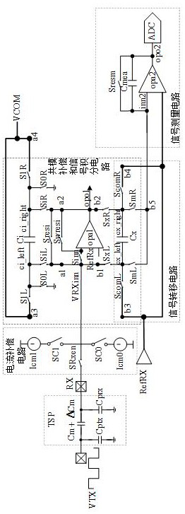
[0038] Embodiment 1 provides a fast capacitive sensing device. The embodiments described below with reference to the accompanying drawings are exemplary, and are only used to explain the present invention, and should not be construed as limiting the present invention. Such as figure 2 and image 3 As shown, the fast capacitive sensing device includes:
[0039] Signal common mode compensation and integration circuit, signal transfer circuit, signal measurement circuit;
[0040] The signal common mode compensation and integration circuit includes an integral capacitor Ci and its switch array, an operational amplifier circuit, a sampling capacitor Cx and its switch array, and the negative input terminal of the operational amplifier circuit is connected to the integral capacitor Ci and its switch array at the same time The first terminal a1 of the sampling capacitor Cx and the first terminal b1 of the switch array thereof, the output terminal of the operational amplifier circuit ...
Embodiment 2
[0046] Embodiment 2 can be further improved on the basis of Embodiment 1, and descriptions of the same or similar parts are omitted. The embodiments described below by referring to the figures are exemplary only for explaining the present invention and should not be construed as limiting the present invention. Specifically, this embodiment includes:
[0047] Please refer to image 3 , the operational amplifier circuit includes a first operational amplifier opal, the positive input terminal of the first operational amplifier is the positive input terminal of the operational amplifier circuit, the negative input terminal of the first operational amplifier is connected to the first end of the switch Sinn, The second terminal of the switch Sinn is the negative input terminal of the operational amplifier circuit, the output terminal of the first operational amplifier is the output terminal of the operational amplifier circuit, and the switch Swresi is connected between the negativ...
Embodiment 3
[0060] Embodiment 3 may be further improved on the basis of Embodiment 1 or Embodiment 2, and descriptions of the same or similar parts are omitted. The embodiments described below by referring to the figures are exemplary only for explaining the present invention and should not be construed as limiting the present invention. Specifically, this embodiment includes:
[0061] Please refer to image 3 , also includes a compensating driving voltage source VCOM connected to the third terminal a3 and the fourth terminal a4 of the integrating capacitor Ci and its switch array.
[0062] The integral capacitor Ci and its switch array also include a switch S1L arranged at the first end of the integral capacitor Ci, and a switch S1R arranged at the second end of the integral capacitor Ci. of the precharge.
[0063] The compensation driving voltage source VCOM is used to precharge the integral capacitor, and the typical compensation charge is VCOM*Ci. It can be seen that the compensati...
PUM
 Abstract
Description
Claims
Application Information
 - R&D
- Intellectual Property
- Life Sciences
- Materials
- Tech Scout
- Unparalleled Data Quality
- Higher Quality Content
- 60% Fewer Hallucinations
Browse by: Latest US Patents, China's latest patents, Technical Efficacy Thesaurus, Application Domain, Technology Topic, Popular Technical Reports.
© 2025 PatSnap. All rights reserved.Legal|Privacy policy|Modern Slavery Act Transparency Statement|Sitemap|About US| Contact US: help@patsnap.com