Voltage source type wind turbine generator frequency modulation and voltage regulation control system and method

A wind turbine, voltage source type technology, applied in the field of wind power generation, can solve problems such as slow response speed, voltage drop at grid connection point, increase in reactive current, etc.

Active Publication Date: 2020-10-30
ZHEJIANG WINDEY
View PDF5 Cites 3 Cited by
  • Summary
  • Abstract
  • Description
  • Claims
  • Application Information

AI Technical Summary

Problems solved by technology

[0003] The shortcomings of the control strategy of grid voltage oriented vector control to track the active power given by the main control are:
[0004] 1. When the system frequency fluctuates, the main control of the wind turbine can only be used to adjust the frequency, and the response speed is slow. Additional frequency adjustment means must be added to meet the system frequency response requirements;
[0005] 2. When the system voltage fluctuates, since the stator side of the doubly-fed motor is directly connected to the grid, when the grid-connected point voltage drops, the stator current will increase in order to follow the power command given by the main controller. If no other control means are added, inject The reactive current of the grid increases, causing a further drop in the grid-connected point voltage

Method used


Image

  • Voltage source type wind turbine generator frequency modulation and voltage regulation control system and method
  • Voltage source type wind turbine generator frequency modulation and voltage regulation control system and method
  • Voltage source type wind turbine generator frequency modulation and voltage regulation control system and method

Examples


Embodiment

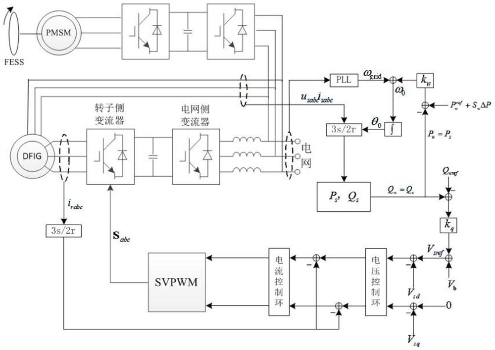
[0070] In this embodiment, a voltage source type wind turbine frequency modulation and voltage regulation control system includes a wind turbine and a flywheel energy storage unit. The flywheel energy storage unit includes a flywheel FESS connected in sequence, a motor PMSM and a motor frequency converter, and the wind turbine stator grid side converter The inverter is electrically connected with the motor inverter, and the rotor side of the wind turbine is electrically connected with the grid through the rotor-side converter and the grid-side converter in turn. The control terminal of the rotor-side converter is connected with the output terminal of the rotor-side SVPWM generator, and the rotor-side SVPWM The input terminal of the generator is connected with the current control loop and the voltage control loop in turn, the control terminal of the motor frequency converter is connected with the output terminal of the motor SVPWM generator, and the input terminal of the motor SV...


PUM


Abstract

The invention relates to a voltage source type wind turbine generator frequency modulation and voltage regulation control system and method. The system comprises a wind turbine generator and a flywheel energy storage unit, the flywheel energy storage unit comprises a flywheel, a motor and a motor frequency converter which are connected in sequence, and a wind turbine generator stator network sideconverter is electrically connected with the motor frequency converter. The method comprises the following steps: initializing a controller; calculating a correlation coefficient; calculating reactivepower given and active power given required during the grid connection of a wind turbine; and carrying out active output and reactive output distribution on the wind turbine generator and the flywheel energy storage unit. The system and the method has the advantages that when the power grid frequency changes, the active output of the wind turbine generator and the flywheel energy storage unit isdistributed according to the influence of the active output change of the wind turbine generator and the flywheel energy storage unit on the grid-connected point frequency, and the output of the windturbine generator is compensated and adjusted; and according to the power grid voltage deviation, the active output and reactive output limitation of the wind turbine generator and the active output and reactive output limitation of the flywheel energy storage unit, the reactive output of a doubly-fed unit and the flywheel energy storage unit is automatically distributed, and the voltage amplitudeof the grid-connected point is improved.

Description

technical field [0001] The invention relates to the technical field of wind power generation, in particular to a voltage source type wind turbine frequency modulation and voltage regulation control system. Background technique [0002] As the penetration rate of wind turbines in the power grid increases, a large number of traditional generators are replaced, and the equivalent moment of inertia of the system becomes smaller, resulting in poor anti-disturbance capabilities of the frequency and voltage of the entire power system. At present, double-fed asynchronous wind turbines (DFIG, Doubly fed Induction Generator) machine-side converters usually use grid voltage oriented vector control to track the active power given by the main control. This control method orients the d-axis of the synchronous rotating coordinate system on the stator voltage vector, ignoring The stator resistance can control the active power output by DFIG by controlling the d-axis component of the rotor c...

Claims


Application Information

Patent Timeline
Patent Type & Authority Applications(China)
IPC IPC(8): H02J3/24H02J3/30H02J3/38H02J3/46H02J3/48H02J3/50
CPCH02J3/24H02J3/241H02J3/30H02J3/381H02J3/466H02J3/48H02J3/50H02J2300/28H02J2203/10Y02E60/16
Inventor 应有法拉蒂尔张晓乐杨靖孙勇
Owner ZHEJIANG WINDEY
Why Eureka
Try Eureka