Battery pack heater for new energy vehicle

A new energy vehicle, battery pack technology, applied in secondary batteries, electrochemical generators, instruments, etc., can solve the problems of insulation layer damage, inability to represent the worst temperature, and untimely response of the control system

Pending Publication Date: 2020-10-30
BORGWARNER EMISSIONS SYST NINGBO CO LTD
View PDF0 Cites 0 Cited by
  • Summary
  • Abstract
  • Description
  • Claims
  • Application Information

AI Technical Summary

Problems solved by technology

Although this solution can meet most applications, for systems with relatively high safety requirements, this open system without flow protection is prone to problems due to instantaneous changes in coolant flow and control system response during actual vehicle operation. Failure to wait for unpredictable working conditions in time will lead to failures such as dry cooling of the coolant, burning of the heating source, and damage to the insulation layer of the heater at low flow rates, which may lead to fire in severe cases
[0003] The hysteresis characteristics of this traditional heating control system lead to the following problems: 1. The failure conduction process is low flow, continuous heating, high temperature, dry burning and burning of the heating source. The existing solution is to monitor the single-point temperature alarm to stop Heating, but considering the low-speed characteristics of the temperature detection circuit itself, and a small number of temperature monitoring points cannot represent the worst temperature under all working conditions, this solution cannot guarantee the safety of products and personnel under all working conditions
In addition, even if a high temperature alarm is detected and measures to stop heating are taken, the product has already formed potential and irreversible damage at the critical temperature; 2. The current battery pack heater control system learns the system flow from the vehicle control system through the communication interface , but because the system flow rate is based on the estimated value of the current motor drive PWM duty cycle, it cannot truly reflect changes such as instantaneous flow reduction at the battery pack heater end due to temperature or waterway valve adjustments.

Method used


Image

  • Battery pack heater for new energy vehicle
  • Battery pack heater for new energy vehicle
  • Battery pack heater for new energy vehicle

Examples


Embodiment Construction

[0019] Embodiments of the present invention are described in detail below, examples of which are shown in the drawings, wherein the same or similar reference numerals designate the same or similar elements or elements having the same or similar functions throughout. The embodiments described below by referring to the figures are exemplary only for explaining the present invention and should not be construed as limiting the present invention.

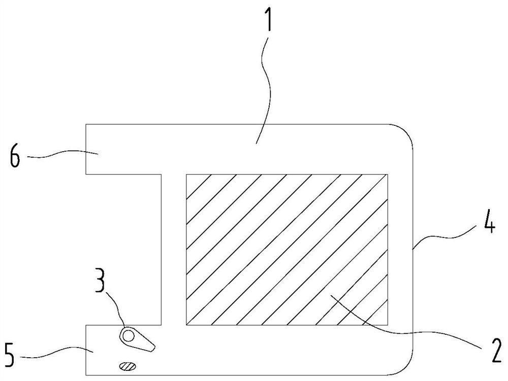
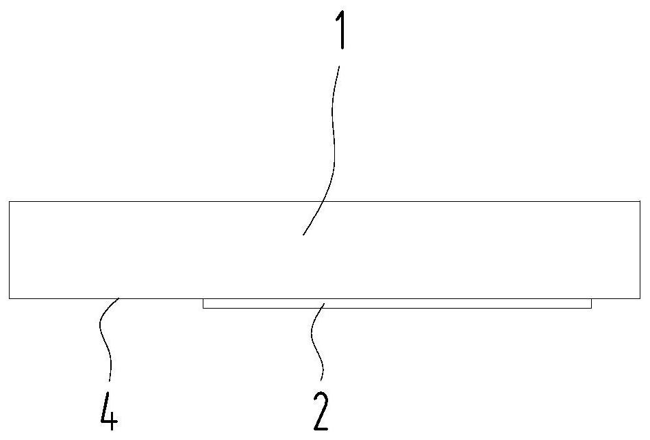
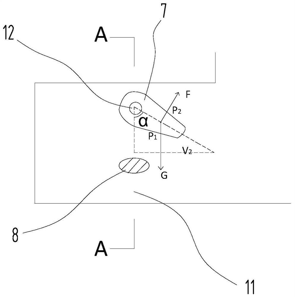
[0020] The invention provides a battery pack heater for a new energy vehicle, such as figure 1 As shown, it includes a cooling liquid channel 1, a heating source 2 and a swing mechanism 3. The channel 1 is formed by a housing 4 to form a sealed channel 1 with a volume. The source 2 is located in the middle of the channel 1, that is, between the inlet 5 and the outlet 6. In this embodiment, the channel 1 is in the shape of a flat box, and the heating source 2 is attached to the side of the box and covers most of the box. When the cooling...


PUM


Abstract

The invention discloses a battery pack heater for a new energy vehicle, which comprises a cooling liquid channel, a heating source and a swing mechanism, wherein the channel is formed by a shell, theheating source is located in the middle outside the channel, two ports of the channel are respectively a cooling liquid inlet and a cooling liquid outlet, the swing mechanism is positioned in the inlet, the swing mechanism comprises a valve plate and a limiting block, the valve plate is rotatably fixed above the inner wall of the inlet, the limiting block is fixed on the inner wall of the inlet and located below the valve plate to prevent the valve plate from turning to the outside of the inlet, the valve plate is provided with magnetic steel, a corresponding Hall sensor is arranged outside the channel, and a bypass liquid path is reserved between the swing mechanism and the inner wall of the inlet. The lightweight swing mechanism is arranged at the cooling liquid inlet to detect the flowof the cooling liquid, so that the control system can monitor the flow of the cooling liquid more accurately, and thus a failure protection program is triggered.

Description

technical field [0001] The invention relates to the technical field of auto parts, in particular to a battery pack heater for new energy vehicles. Background technique [0002] Traditional battery pack heaters usually screen-print (or coat) the detection material and its insulating layer on the outer surface of the coolant flow channel, and adjust the power of the heating source through the designed circuit and program to control the outlet water temperature. It can quickly heat the battery pack of new energy vehicles to the optimal working temperature. Although this solution can meet most applications, for systems with relatively high safety requirements, this open system without flow protection is prone to problems due to instantaneous changes in coolant flow and control system response during actual vehicle operation. Failure to wait for unpredictable working conditions in time will lead to failures such as dry cooling of the coolant, burning of the heating source, and d...

Claims


Application Information

Patent Timeline
IPC IPC(8): H01M10/615H01M10/625H01M10/635H01M10/637H01M10/6568H01M10/48G01F1/00G01R33/07
CPCH01M10/615H01M10/625H01M10/635H01M10/637H01M10/6568H01M10/48G01F1/00G01R33/07Y02E60/10
Inventor 张飞丁晓勇郭严严
Owner BORGWARNER EMISSIONS SYST NINGBO CO LTD
Why Eureka
Try Eureka