I2C deadlock and recovery method and device
A deadlock, optical module technology, applied in instruments, electrical digital data processing and other directions, can solve the problem of extra hardware circuit, I2C deadlock can not be found in time, etc.
- Summary
- Abstract
- Description
- Claims
- Application Information
AI Technical Summary
Problems solved by technology
Method used
Image
Examples
Embodiment 1
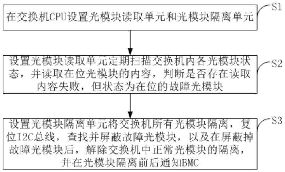
[0062] Such as figure 1 As shown, the present invention provides a kind of I2C deadlock and recovers the method, comprises the steps:
[0063] S1. Set the optical module reading unit and the optical module isolation unit on the switch CPU;
[0064] S2. Set the optical module reading unit to regularly scan the status of each optical module in the switch, and read the content of the optical module in place, and judge whether there is a faulty optical module that failed to read the content, but the status is in place;
[0065] S3. Set the optical module isolation unit to isolate all optical modules of the switch, reset the I2C bus, find and shield the faulty optical module, and after shielding the faulty optical module, release the isolation of the normal optical module in the switch, and notify before and after the isolation of the optical module BMC.
Embodiment 2
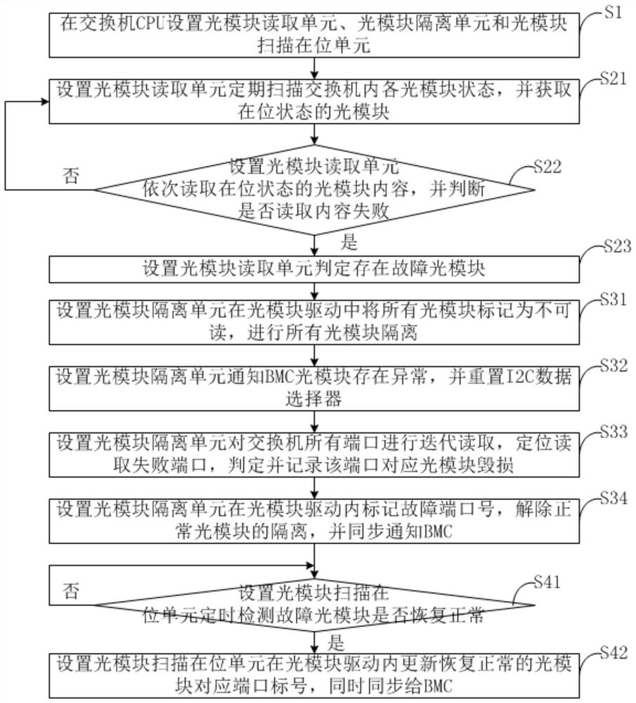
[0067] Such as figure 2 As shown, the present invention provides a kind of I2C deadlock and recovers the method, comprises the steps:
[0068] S1. Set the optical module reading unit, the optical module isolation unit and the optical module scanning in-position unit on the switch CPU;
[0069] S2. Set the optical module reading unit to regularly scan the status of each optical module in the switch, and read the content of the optical module in place, and judge whether there is a faulty optical module that failed to read the content, but the status is in place; the specific steps are as follows:
[0070] S21. Set the optical module reading unit to regularly scan the status of each optical module in the switch, and obtain the optical module in the in-position state;
[0071] S22. Set the optical module reading unit to read the content of the optical module in the in-position state sequentially, and judge whether the reading of the content fails;
[0072] If so, go to step S23...
Embodiment 3
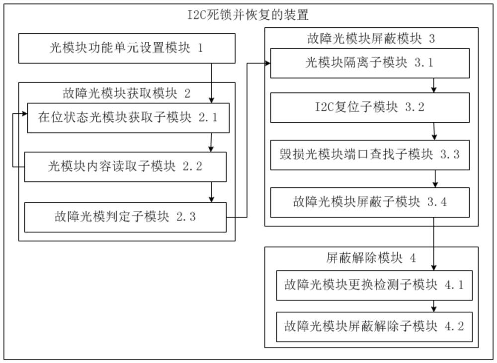
[0086] Such as image 3 As shown, the present invention provides a device for I2C deadlock and recovery, including:
[0087] The optical module function unit setting module 1 is used to set the optical module reading unit, the optical module isolation unit and the optical module scanning in-position unit on the switch CPU;
[0088] Faulty optical module acquisition module 2, used to set the optical module reading unit to regularly scan the status of each optical module in the switch, and read the content of the optical module in place, and judge whether there is a faulty optical module that failed to read the content, but the status is in place Module; faulty optical module acquisition module 2 includes:
[0089] The in-position state optical module acquisition sub-module 2.1 is used to set the optical module reading unit to periodically scan the status of each optical module in the switch, and obtain the optical module in the in-position state;
[0090] The optical module c...
PUM
 Abstract
Description
Claims
Application Information
 - Generate Ideas
- Intellectual Property
- Life Sciences
- Materials
- Tech Scout
- Unparalleled Data Quality
- Higher Quality Content
- 60% Fewer Hallucinations
Browse by: Latest US Patents, China's latest patents, Technical Efficacy Thesaurus, Application Domain, Technology Topic, Popular Technical Reports.
© 2025 PatSnap. All rights reserved.Legal|Privacy policy|Modern Slavery Act Transparency Statement|Sitemap|About US| Contact US: help@patsnap.com


