
Optical machine assembly of projection equipment and projection equipment

A technology of projection equipment and components, applied in optics, instruments, projection devices, etc., can solve problems such as the reduction of the clarity and resolution of the projected picture, and the inability to meet the requirements of picture quality, so as to avoid the reduction of the clarity and resolution and ensure the work. normal effect

Active Publication Date: 2020-10-30
QINGDAO HISENSE LASER DISPLAY CO LTD
View PDF6 Cites 6 Cited by
  • Summary
  • Abstract
  • Description
  • Claims
  • Application Information

AI Technical Summary

Problems solved by technology

[0005] An embodiment of the present invention provides an optical-mechanical component of a projection device and a projection device, which are used to solve the problem that the definition and resolution of the projected picture will decrease after the existing projection device works for a period of time, and the picture quality cannot be met. question

Method used


Image

  • Optical machine assembly of projection equipment and projection equipment
  • Optical machine assembly of projection equipment and projection equipment
  • Optical machine assembly of projection equipment and projection equipment

Examples


Embodiment Construction

[0025] The following will clearly and completely describe the technical solutions in the embodiments of the present invention with reference to the accompanying drawings in the embodiments of the present invention. Obviously, the described embodiments are only some, not all, embodiments of the present invention. Based on the embodiments of the present invention, all other embodiments obtained by persons of ordinary skill in the art without making creative efforts belong to the protection scope of the present invention.

[0026] In describing the present invention, it is to be understood that the terms "center", "upper", "lower", "front", "rear", "left", "right", "vertical", "horizontal", The orientations or positional relationships indicated by "top", "bottom", "inner", "outer", etc. are based on the orientations or positional relationships shown in the drawings, and are only for the convenience of describing the present invention and simplifying the description, rather than in...


PUM


Abstract

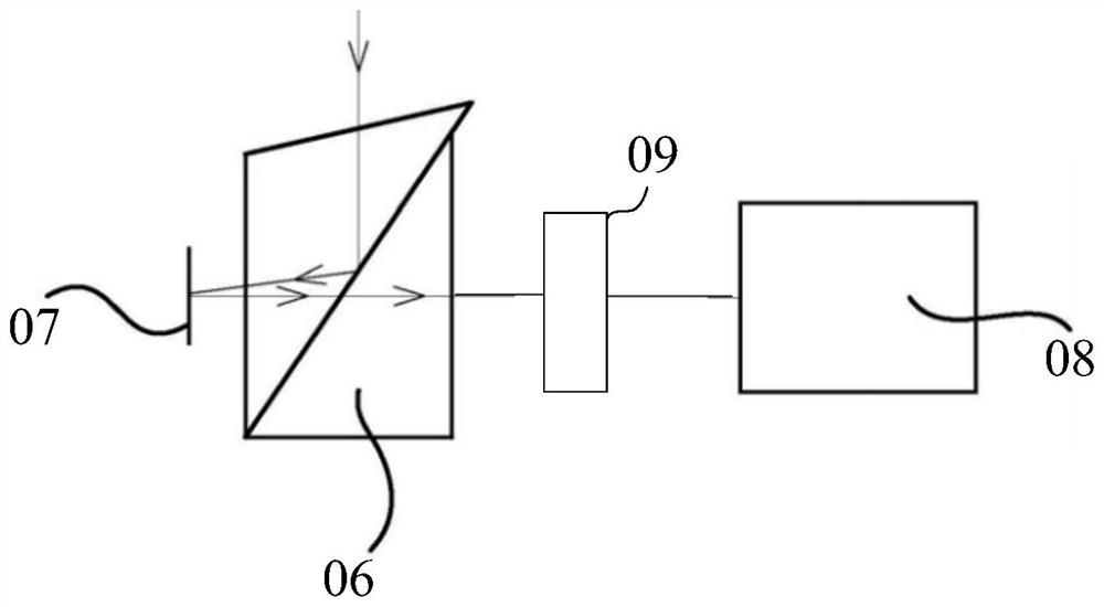
The invention discloses an optical machine assembly of projection equipment and the projection equipment, relates to the technical field of the projection equipment, and aims to solve the problems that the definition and the resolution of a projection picture are reduced after the existing projection equipment works for a period of time, and the picture quality requirement cannot be met. The optical machine assembly of the projection equipment comprises a digital micro-mirror element, a galvanometer assembly, a shielding piece and a heat dissipation device, wherein the galvanometer assembly comprises a galvanometer, the galvanometer is located on the light path of first reflected light, the first reflected light is the light reflected when a micro lens of the digital micro-mirror element is in an on state, the shielding piece is located on the light incident side of the galvanometer assembly, located outside the light path of the first reflected light and located on the light path of second reflected light so as to shield the second reflected light, the second reflected light is the light reflected when the micro lens of the digital micro-mirror element is in an off state, and theheat dissipation device is used for dissipating heat of the shielding piece. The optical machine assembly can be used in the projection equipment.

Description

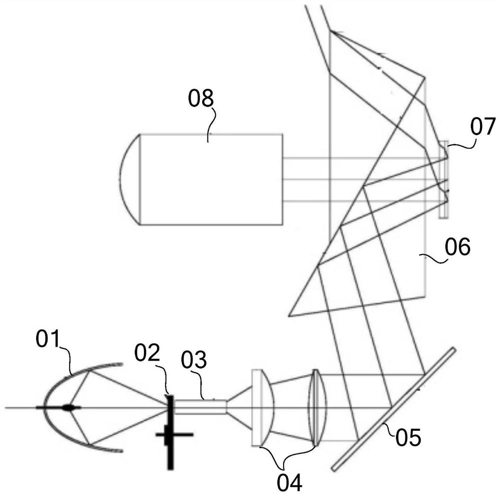
technical field [0001] The invention relates to the technical field of projection equipment, in particular to an optical-mechanical component of the projection equipment and the projection equipment. Background technique [0002] Digital Light Processing projector (Digital Light Processing referred to as DLP) is a technology based on digital micromirror device (Digital Micromirror Device referred to as DMD) to complete the display of visual digital information. The principle is: for example figure 1 As shown, the white light generated by the light source 01 is divided into three primary colors of red, green and blue through the color wheel 02, and the three primary colors pass through the light collecting rod 03, the relay optical system 04, the mirror 05 and the TIR (Total Internal Reflection, total internal reflection) prism After group 06, it is projected onto the digital micromirror element 07. The digital micromirror element 07 is composed of many microlenses. One micr...

Claims


Application Information

Patent Timeline
IPC IPC(8): G03B21/00G03B21/16
CPCG03B21/008G03B21/16G03B21/00
Inventor 刘祥彬戴洁
Owner QINGDAO HISENSE LASER DISPLAY CO LTD
Learn More