
Highway surface marking and spraying device and using method thereof

A spraying device, road technology, applied in the direction of road surface cleaning, roads, roads, etc., can solve the problems of excessive marking, waste, high cost, etc.

Inactive Publication Date: 2020-10-30
郭云美
View PDF6 Cites 0 Cited by
  • Summary
  • Abstract
  • Description
  • Claims
  • Application Information

AI Technical Summary

Problems solved by technology

[0003] The current scribing and spraying device can only draw a line of one depth, which has certain limitations when scribing different road surfaces, and when loading the paint, there is no specific amount of loading , leading to more left over markings, more waste, and greater costs

Method used


Image

  • Highway surface marking and spraying device and using method thereof
  • Highway surface marking and spraying device and using method thereof
  • Highway surface marking and spraying device and using method thereof

Examples


Embodiment 1

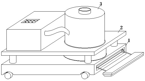
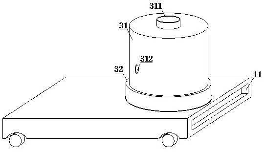
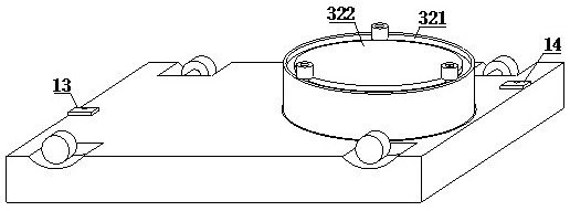
[0034] refer to figure 1 , 2 , 3, 5 and 6, a road surface marking spraying device, comprising a base plate 1, a support mechanism 2 and a barrel mechanism 3, the support mechanism 2 and the barrel mechanism 3 are all arranged on the upper surface of the base plate 1, the base plate 1 includes a connection groove 11, a pre-cleaning mechanism 12, a starting point determination module 13 and an end point calculation module 14. A connection groove 11 is opened on one side of the base plate 1, and a pre-cleaning mechanism 12 is arranged inside the connection groove 11. The bottom of the base plate 1 A starting point determination module 13 and an end point calculation module 14 are fixedly installed on the bottom surface, and the support mechanism 2 includes a support plate 21, a support rod 22 and a control box 23, and a support rod 22 is fixedly installed on the lower bottom surface of the support plate 21. The surface is provided with a control box 23, and the support plate 21 ...

Embodiment 2

[0036] refer to figure 2 , 4 And 8, the storage tube 31 includes a feed port 311, an external interface 312, a liquid level sensing module 313, a liquid level gauge 314, a Z-shaped tube 315 and a feeding tube 316, and the upper surface of the storage tube 31 is provided with a feed port 311, The outer surface of the storage tube 31 is provided with an external interface 312, the liquid level sensing module 313 and the liquid level gauge 314 are all arranged on the inner wall of the storage tube 31, and the inside of the storage tube 31 is provided with a Z-shaped tube 315, and the bottom of the storage tube 31 The bottom surface is provided with a feeding tube 316, the storage tube 31 communicates with the spraying tube 32 through the feeding tube 316, one end of the Z-shaped tube 315 is connected with the external interface 312, and the other end of the Z-shaped tube 315 is connected with the feeding tube 316. Connected, the storage tube 31 is connected with the control box...

Embodiment 3

[0038] refer to Figure 5 and 8 , the control center 231 includes a distance measurement module 2311, a road surface sensing module 2312 and a speed adjustment module 2313, the distance measurement module 2311 is electrically connected with the starting point determination module 13 and the end point calculation module 14, and the starting point determination module 13 and the end point calculation module 14 are connected to the liquid level The sensing module 313 is electrically connected, and the lower bottom surface of the spraying tube 32 is provided with an arc groove 321 , and the inside of the arc groove 321 is provided with a rotating seat 322 , and the rotating seat 322 communicates with the storage barrel 31 through the feeding tube 316 .


PUM


Abstract

The invention discloses a highway surface marking and spraying device. An existing marking and spraying device can only draw lines with one depth, certain limitation exists when marking is performed on different road surfaces, and when pigment is loaded into a cylinder, cylinder loading without a specific magnitude exists so that more marking residues are left, more waste is caused, and cost is large. In the invention, an air pump in a control box and a control valve in a first-stage spray cylinder are opened so as to perform a first spray; after the first spray is completed, the control valveof the first-stage spray cylinder is closed; the control valve of a second-stage spray cylinder is opened so as to complete a second spray; and finally, the control valve of the second-stage spray cylinder is closed, the control valve of a third-stage spray cylinder is opened, the lines with different color depths can be scribed, an original point of marking is determined by utilizing an originalpoint determining module, and a specific length of the marking road surface is calculated by utilizing an end point calculating module after an end point is reached so that an equal amount of markingpigment can be accurately injected.

Description

technical field [0001] The invention relates to the technical field of road marking, in particular to a road surface marking and spraying device and a method for using the same. Background technique [0002] Highway marking refers to the use of lines, arrows, text, facade marks, raised road signs and outline marks on the road surface to convey traffic information such as guidance, restrictions, and warnings to traffic participants. Its role is to control and guide traffic. , can be used in conjunction with signs, or can be used alone. Hot-melt marking is now one of the most widely used marking types for road marking in China. Road marking is mainly drawn on the road surface, which is exposed to the sun, rain, wind The snow is frozen and subjected to the impact and wear of vehicles, so there are strict requirements on its performance. Firstly, it requires short drying time and simple operation to reduce traffic interference; secondly, it requires strong reflective performance...

Claims


Application Information

Patent Timeline
IPC IPC(8): E01C23/22E01H1/00
CPCE01C23/22E01H1/00
Inventor 郭云美
Owner 郭云美
Learn More