
Electrolytic device and clothes treatment equipment

A technology of clothes treatment equipment and electrolysis device, which is applied in the direction of washing device, water/sewage treatment, water/sludge/sewage treatment, etc., which can solve the problems of electrolysis efficiency drop, failure, and large space occupied by electrode devices, so as to achieve extended use Effects of life, protection against contact short circuit, and improvement of design flexibility

Active Publication Date: 2020-10-30
WUXI LITTLE SWAN ELECTRIC CO LTD
View PDF2 Cites 1 Cited by
  • Summary
  • Abstract
  • Description
  • Claims
  • Application Information

AI Technical Summary

Problems solved by technology

In the related art, using electrodes to electrolyze water in the washing machine can generate hydroxyl radicals for sterilization, but the efficiency is very low, the electrode device takes up a lot of space, and the lint is easy to block the electrode. After a period of use, the amount of lint blocked becomes larger More and more, the effective working area of ​​the electrolytic cathode surface decreases, the electrolytic efficiency decreases, or even fails, and the service life is shorter

Method used


Image

  • Electrolytic device and clothes treatment equipment
  • Electrolytic device and clothes treatment equipment
  • Electrolytic device and clothes treatment equipment

Examples


no. 1 example

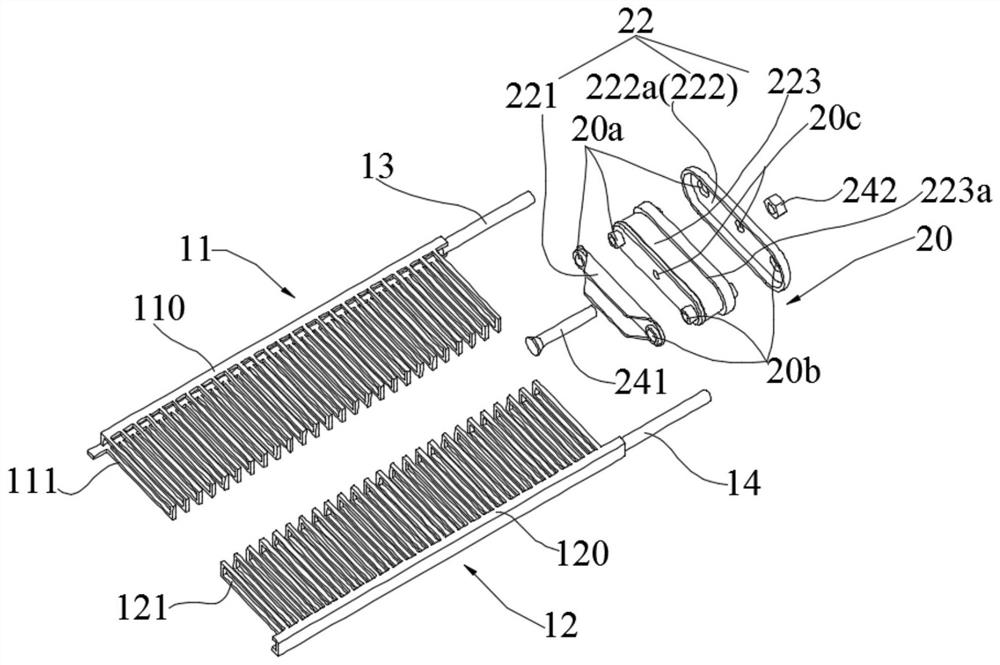
[0090] see Figure 1 to Figure 14 The extension direction of the anode conductive connector 14 and the cathode conductive connector 13 is approximately perpendicular to the plane where the first support portion 110 and the second support portion 120 are located, that is, the cathode conductive connector 13 and the anode conductive connector 14 are approximately along the outer cylinder 30 The axial extension of the electrolysis device 10 is firmly connected with the closed end of the outer cylinder 30 through the installation device 20 .

[0091] For some miniaturized laundry treatment equipment, the space between the inner cylinder and the outer cylinder 30 may be relatively narrow, and in order to generate enough hydroxyl radicals by electrolysis, the electrolysis device 10 needs to have a sufficient working surface area. In the embodiment of the present application, since the electrolysis cathode 11 and the electrolysis anode 12 adopt a layered structure and have a certain ...

no. 2 example

[0099] see Figure 15 to Figure 17 The difference from the first embodiment is that in this embodiment, the cathode conductive connector 13 and the anode conductive connector 14 extend approximately along the radial direction of the outer cylinder 30, that is to say, the cathode conductive connector 13 is approximately perpendicular to the first The support part 110 and the anode conductive connecting body 14 are substantially perpendicular to the second support part 120 , and the electrolysis device 10 is fastened and connected to the outer cylinder 30 through the installation device 20 in the circumferential direction.

[0100] see Figure 15 , the cathode conductive connector 13 and the anode conductive connector 14 are approximately perpendicular to the plane where the electrolytic cathode 11 and the electrolytic anode 12 are located, the electrolytic cathode 11 abuts on the cathode conductive connector 13, and the electrolytic anode 12 abuts on the anode conductive connec...


PUM


Abstract

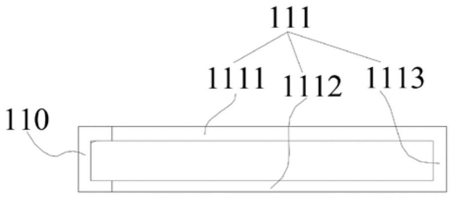
The embodiment of the invention provides an electrolytic device and clothes treatment equipment. The electrolytic device comprises an electrolytic cathode and an electrolytic anode. The electrolytic cathode comprises a first supporting part and one or more first comb teeth extending from the first supporting part to the direction away from the first supporting part, the first comb teeth are arranged at intervals in the length direction of the first supporting part, the first comb teeth comprise first branch teeth and second branch teeth, and the first branch teeth and the second branch teeth are arranged at intervals in the thickness direction of the electrolytic cathode; and the electrolytic anode comprises a second supporting part and one or more second comb teeth extending from the second supporting part to the direction away from the second supporting part, the second comb teeth are arranged at intervals in the length direction of the second supporting part, the second comb teeth comprise third branch teeth and fourth branch teeth, and the third branch teeth and the fourth branch teeth are arranged at intervals in the thickness direction of the electrolytic anode. According tothe electrolytic device, floc is not prone to blocking the electrolytic device, and the service life of the electrolytic device can be prolonged; and the contact short circuit between the electrolyticcathode and the electrolytic anode can further be effectively prevented.

Description

technical field [0001] The present application relates to the technical field of electrolytic sterilization, in particular to an electrolytic device and clothes treatment equipment. Background technique [0002] Sterilization technologies commonly used in washing machines include silver ion sterilization technology, ozone technology, ultraviolet sterilization, etc. Among them, silver ion sterilization technology enters the washing tub through silver ions with water flow, and silver ions destroy the bacterial cell wall in the clothes stains to achieve the sterilization effect. However, silver ions in the laundry solution cannot kill all cells, and there is a risk of silver ions remaining; ozone sterilization uses the oxidation of oxygen atoms to destroy the structure of microbial membranes to achieve bactericidal effects, but only a part of ozone dissolves in water, Most of it escapes into the air, and the increase in ozone content in the air will harm human health; ultraviol...

Claims


Application Information

Patent Timeline
Patent Type & Authority Applications(China)
IPC IPC(8): D06F35/00C02F1/461
CPCD06F35/003C02F1/4618C02F2001/46185
Inventor 高久兴熊明杨青波周存玲王嘉
Owner WUXI LITTLE SWAN ELECTRIC CO LTD
Learn More