Eureka AIR delivers breakthrough ideas for toughest innovation challenges, trusted by R&D personnel around the world.

A high-efficiency power equipment maintenance device and its application method

A technology for power equipment and maintenance devices, which is applied to mechanical equipment, lifting devices, switchgear, etc., and can solve problems such as increasing the risk of manual maintenance

Active Publication Date: 2022-04-29
云南量坤售电服务有限公司
View PDF18 Cites 0 Cited by
  • Summary
  • Abstract
  • Description
  • Claims
  • Application Information

AI Technical Summary

Problems solved by technology

[0004] Some current electrical equipment is often installed in a higher position, and when the electrical equipment needs to be repaired manually, it is often necessary to climb up the electrical equipment with the help of climbing tools for maintenance, and this operation will undoubtedly increase the labor of manual maintenance. risk, so we propose a high-efficiency power equipment maintenance device and its use method to solve the above-mentioned problems

Method used


Image

  • A high-efficiency power equipment maintenance device and its application method
  • A high-efficiency power equipment maintenance device and its application method
  • A high-efficiency power equipment maintenance device and its application method

Examples


Embodiment 1

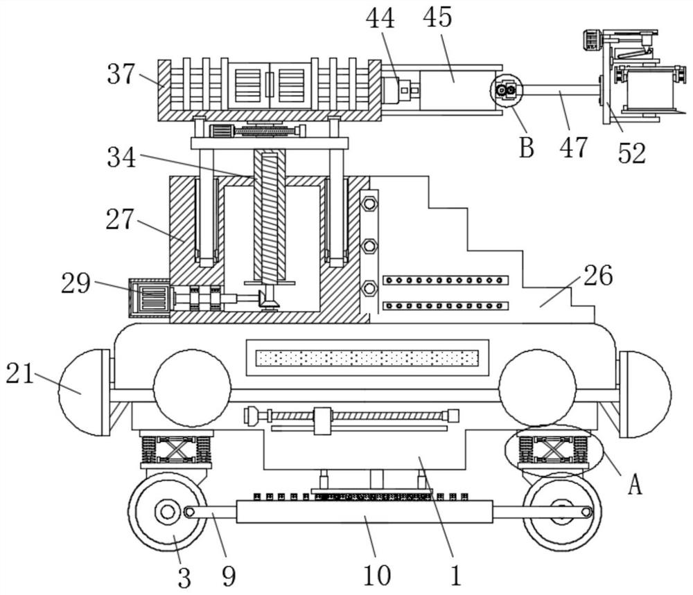
[0048] Embodiment one: if figure 1As shown, a high-efficiency power equipment maintenance device includes a moving base 1, a plurality of hollow elastic balls 21 are fixedly connected to the outer side of the moving base 1, buffer assemblies are arranged on the four corners of the bottom of the moving base 1, and the buffering The bottom of the assembly is fixedly connected with a universal wheel 3, and the rotation on one side of the two universal wheels 3 on the same side deviated from the center of the circle is connected with the same connecting rod 9, and the connecting rod 9 is provided with a brake plate 10 and a moving seat 1 A mounting groove 11 is provided at the bottom of the mounting groove 11, a sliding rod 12 is fixedly connected to the inner wall of the top of the mounting groove 11, and a pushing block 13 is slidably connected to the sliding rod 12, and one side of the moving seat 1 is fixedly connected with a horizontal moving position for adjusting the pushing...

Embodiment 2

[0065] Embodiment two: if Figure 7 As shown, two buffer springs 24 symmetrically arranged are fixedly connected to one side of the inner wall of the hollow elastic ball 21, and one side of the two buffer springs 24 is fixedly connected to the same buffer plate 22, and one side of the buffer plate 22 There are three fixed plates 23 fixedly connected, and the other ends of the three fixed plates 23 are fixedly connected with the side wall of the inner cavity of the hollow elastic ball 21, and one side of the buffer plate 22 is fixedly connected with two symmetrically arranged buffer sheets 25, and The two buffer springs 24 are located between the two buffer pieces 25 , and the other end of the buffer piece 25 is fixedly connected to one inner wall of the hollow elastic ball 21 .


PUM


Abstract

The invention discloses a high-efficiency power equipment maintenance device, which includes a moving seat, a plurality of hollow elastic balls are fixedly connected in a ring on the outer side of the moving seat, buffer assemblies are arranged at four corners of the bottom of the moving seat, And the bottom of the buffer assembly is fixedly connected with universal wheels, and the one side of the two universal wheels on the same side is connected with the same connecting rod for rotation away from the center of the circle. The connecting rod is provided with a brake plate, and the moving seat There is a mounting groove at the bottom of the mounting groove, and a sliding rod is fixedly connected to the inner wall of the top of the mounting groove, and a pushing block is slidably connected to the sliding rod; the present invention is simple in operation, compact in structure, and has the functions of moving, lifting, adjusting angle and maintenance The function of clamping and fixing electric power equipment is rich in functions, which fully meets the needs of power equipment maintenance personnel and has broad market promotion prospects.

Description

technical field [0001] The invention relates to the technical field of power equipment maintenance, in particular to a high-efficiency power equipment maintenance device and a use method thereof. Background technique [0002] Power equipment mainly includes power generation equipment and power supply equipment. Power generation equipment is mainly power plant boilers, steam turbines, gas turbines, water turbines, generators, transformers, etc. Power supply equipment is mainly transmission lines of various voltage levels, transformers, contactors, etc. device and so on. [0003] The planned maintenance system adopted by most power equipment in the power system has serious defects, such as frequent temporary maintenance, insufficient or excessive maintenance, blind maintenance, etc., which makes countries in the world spend a lot of money on equipment maintenance every year. How to reasonably arrange the maintenance of power equipment, save maintenance costs, reduce maintenan...

Claims


Application Information

Patent Timeline
Patent Type & Authority Patents(China)
IPC IPC(8): B66F11/04B66F13/00F16F15/067F16F15/02B66C23/06B66C23/62B66C23/82B66C23/90B66C1/10B66C1/42H02B3/00
CPCB66F11/04B66F13/00F16F15/067F16F15/02B66C23/06B66C23/62B66C23/828B66C23/905B66C1/10B66C1/425H02B3/00
Inventor 不公告发明人
Owner 云南量坤售电服务有限公司
Why Eureka
Eureka Blog
Learn More