A car front suspension beam

A front suspension and beam technology, applied in vehicle parts, substructure, transportation and packaging, etc., can solve the problems of difficult to control molding accuracy, poor automotive NVH performance, complex structure, etc., to reduce acceleration roar, reduce cutting waste, The effect of enhancing comfort

Active Publication Date: 2022-04-19
ZHEJIANG GEELY HLDG GRP CO LTD +1
View PDF14 Cites 0 Cited by
  • Summary
  • Abstract
  • Description
  • Claims
  • Application Information

AI Technical Summary

Problems solved by technology

Although the front beam can isolate the vibration of the engine to a certain extent, there are still some deficiencies: the upper sheet metal and the lower sheet metal are welded by flanging, so the upper sheet metal and lower sheet metal of the front beam are designed in two directions. An "Ω"-shaped stamping part has a complex structure, difficult forming, and difficult to control the forming accuracy. Therefore, it is difficult to ensure high assembly accuracy of the upper and lower sheet metals, which will lead to poor NVH performance of the car and cannot meet the current driving requirements. The comfort requirements of the personnel in the compartment; in addition, a reinforcing plate is provided on the inner surface of the middle part of the front cross member, so that the part where the upper sheet metal is connected to the reinforcing plate is not easily deformed, but because the reinforcing plate is only connected to the upper sheet metal, resulting in suspension The Z-direction dynamic stiffness of the installation point is difficult to guarantee, the vibration isolation effect on the engine is low, and the phenomenon of acceleration and roar in the cabin cannot be well improved, which affects the NVH performance of the car.

Method used


Image

  • A car front suspension beam
  • A car front suspension beam
  • A car front suspension beam

Examples


Embodiment Construction

[0027] The following is a specific embodiment of the present invention and in conjunction with the accompanying drawings, further describes the technical solution of the present invention, but the present invention is not limited to this embodiment.

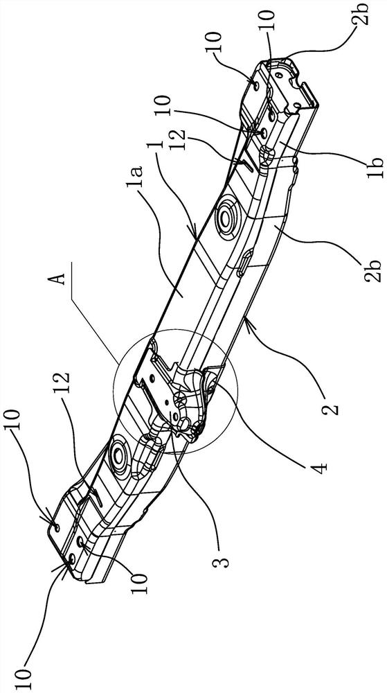
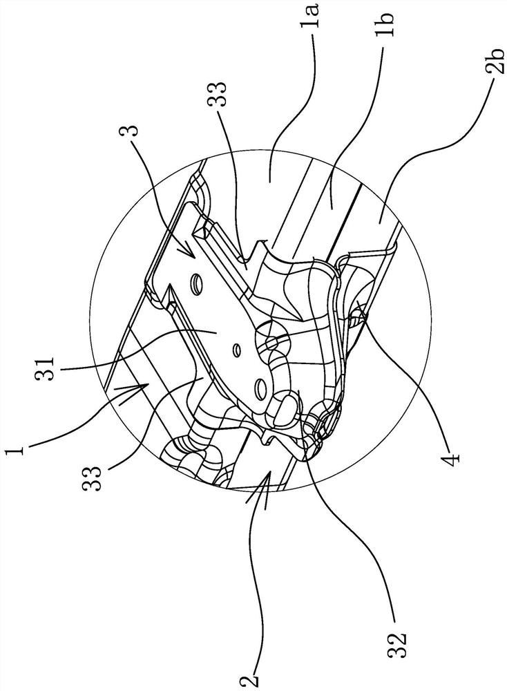
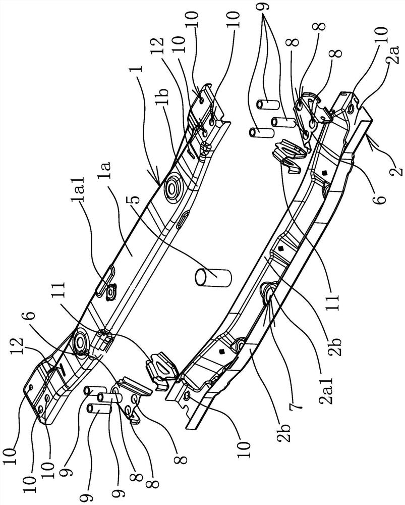
[0028] Such as figure 1 and figure 2 As shown, the front suspension crossbeam of the automobile comprises a crossbeam upper plate 1 and a crossbeam lower plate 2. There is a suspension installation upper plate 3, and the crossbeam lower plate 2 is fixedly connected with a suspension installation lower plate 4 supporting the suspension installation upper plate 3, and the suspension installation upper plate 3 is fixedly connected with the suspension installation lower plate 4.

[0029] Such as figure 2 As shown, the suspension installation upper plate 3 includes a longitudinal top plate 31, the other end of the longitudinal top plate 31 extends to the side of the beam upper plate 1 and has a bent plate body 32 bent downward rel...


PUM


Abstract

The invention provides an automobile front suspension beam, which belongs to the technical field of automobiles. It solves the problems in the prior art that the front suspension beam is difficult to form and the effect of isolating engine vibration is low. The front suspension crossbeam of the automobile includes a crossbeam upper plate and a crossbeam lower plate. The crossbeam upper plate and the crossbeam lower plate are fixedly connected to each other to form a long hollow beam structure. The top surface of the crossbeam upper plate is fixedly connected with a suspension installation upper plate. The lower plate of the crossbeam is fixedly connected with the lower plate of the suspension installation supporting the upper plate of the suspension installation, and the upper plate of the suspension installation is fixedly connected with the lower plate of the suspension installation. The reinforcing sleeve arranged in the opposite direction is located under the upper plate of the suspension installation and is fixedly connected with the upper plate of the beam and the lower plate of the beam respectively. The invention can better isolate the vibration generated by the engine, improve the NVH performance of the automobile, and has the advantages of convenient manufacture.

Description

technical field [0001] The invention belongs to the technical field of automobiles and relates to an automobile front suspension beam. Background technique [0002] With the development of science and technology and the improvement of people's living standards, cars have entered thousands of households and become the most important means of transportation for people's daily travel. The sub-frame of the car is a component of the front and rear axles of the car. The design of the sub-frame allows the front and rear suspensions to be assembled on the sub-frame to form an axle assembly, and then the assembly is installed on the body together to give Installation brings convenience. [0003] The front suspension beam is an important part of the sub-frame of the car. It provides a mounting point for the powertrain of the vehicle, carries part of the weight of the powertrain, and transmits the moment from the powertrain. At the same time, the front suspension beam is also a buffe...

Claims


Application Information

Patent Timeline
Patent Type & Authority Patents(China)
IPC IPC(8): B62D21/02B62D21/11
CPCB62D21/02B62D21/11
Inventor 韩微微汤小生
Owner ZHEJIANG GEELY HLDG GRP CO LTD
Why Eureka
Try Eureka