
Anti-torque pull rod and mounting structure thereof

A technology of anti-torsion tie rod and installation structure, which is applied in the direction of control device, power device, transportation and packaging, etc. It can solve the problems of poor NVH performance and poor dynamic stiffness of torsion tie rod installation structure, and achieve good support and reinforcement, dynamic stiffness Good results

Pending Publication Date: 2020-10-30
GUANGZHOU AUTOMOBILE GROUP CO LTD
View PDF0 Cites 2 Cited by
  • Summary
  • Abstract
  • Description
  • Claims
  • Application Information

AI Technical Summary

Problems solved by technology

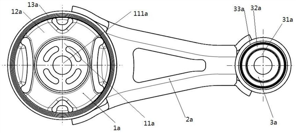
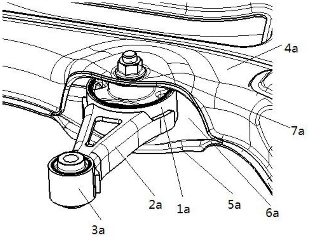
Since the first inner tube 11a is a stationary part, and the first outer tube 13a and the tie rod bracket 2a will move relative to the sub-frame, in order to avoid the movement interference between the first outer tube 13a, the tie rod bracket 2a and the sub-frame, the auxiliary The vehicle frame and the first outer tube 13a and the tie rod support 2a need to leave enough clearance, image 3 In the Y direction (the width direction of the car, that is image 3 left and right direction), the sub-frames on both sides and the two sides of the first outer tube 13a need to leave a Y-direction gap of more than 10mm, so that the dynamic stiffness of the torsion tie rod installation structure in the Y direction is relatively poor
In addition, because only the first inner tube 11a is connected with the subframe, the first outer tube 13a is not connected with the subframe, and the Z direction (height direction of the automobile) is between the first outer tube 13a and the subframe. , that is image 3 There is also a large gap in the up and down direction), which makes the dynamic stiffness of the torsion tie rod installation structure in the Z direction poor. When the engine rotates at a high speed, there will be a roar in the car, which makes the NVH performance of the whole vehicle poor.

Method used


Image

  • Anti-torque pull rod and mounting structure thereof
  • Anti-torque pull rod and mounting structure thereof
  • Anti-torque pull rod and mounting structure thereof

Examples


Embodiment Construction

[0022] The specific implementation manners of the present invention will be further described in detail below in conjunction with the accompanying drawings and embodiments. The following examples are used to illustrate the present invention, but are not intended to limit the scope of the present invention.

[0023] Such as Figure 5 , 6 As shown, the torsion-resistant tie rod according to an embodiment of the present invention includes a large-end bush 7 , a small-end bush 4 , and a tie-rod bracket 3 connected between the big-end bush 7 and the small-end bush 4 .

[0024] The big-end bushing 7 is used to be connected with the auxiliary frame, and the big-end bushing includes the big-end bushing inner tube 31, the big-end bushing rubber body 2 wrapped outside the big-end bushing inner tube 31 and the big-end bushing rubber body 2 wrapped around the big-end bushing. Cover rubber body 2 outer big end liner outer tube 1. The outer tube 1 of the large-end bushing has a notch 12,...


PUM


Abstract

The invention provides an anti-torque pull rod, which comprises a large-end bushing, a small-end bushing and a pull rod bracket, wherein the large-end bushing comprises a large-end bushing inner pipe,a large-end bushing rubber body and a large-end bushing outer pipe; the large-end bushing outer pipe is provided with a notch, one end of the pull rod bracket penetrates through the notch to be connected with the large-end bushing inner pipe, the other end of the pull rod bracket is connected with the small-end bushing, the large-end bushing outer pipe is provided with a first fixing hole, and the first fixing hole is used for allowing a fixing piece to penetrate through and fixing the large-end bushing outer pipe to an auxiliary frame. The invention further discloses an anti-torque pull rodmounting structure. The anti-torque pull rod of the anti-torque pull rod mounting structure is the anti-torque pull rod; the anti-torsion pull rod mountingstructure further comprises an auxiliary frame, the auxiliary frame comprises an upper layer plate and a lower layer plate, the upper layer plate and the lower layer plate form a mounting opening, second fixing holes are formed in the upper layer plate and the lower layer plate, the large-end bushing is arranged in the mountingopening, and the fixing piece penetrates through the first fixing hole and the second fixing hole to fix the large-end bushing outer pipe to the auxiliary frame.

Description

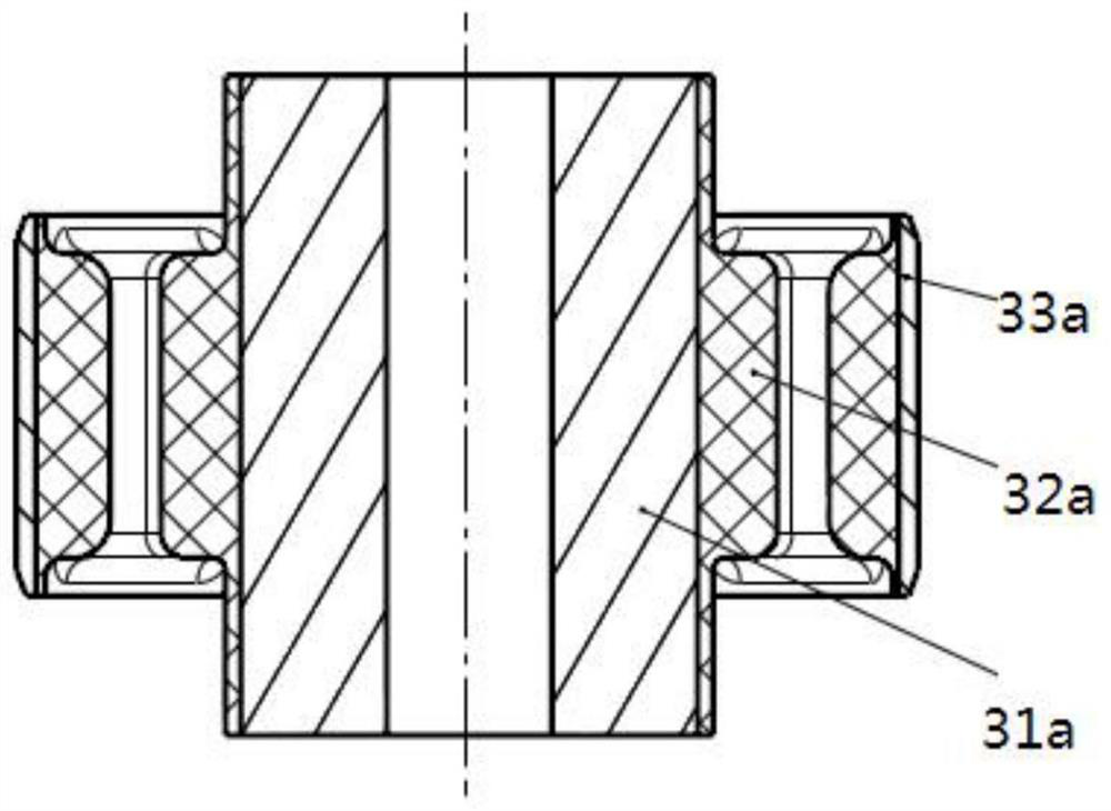
technical field [0001] The invention relates to the field of automobiles, in particular to a torsion-resistant tie rod and its installation structure. Background technique [0002] Automotive powertrain suspension system usually includes left suspension, right suspension and torsion tie rod. Among them, the anti-torsion tie rod is arranged under the power assembly, including the big end bush, the small end bush and the tie rod bracket. The small end bushing is connected to the transmission or engine, and the big end bushing is connected to the subframe. The torsional tie rod reduces the vibration transmitted from the powertrain to the subframe through the bushings at both ends, thereby improving the NVH performance of the vehicle. At the same time, when the engine outputs torque, the anti-torsion tie rod also plays a role in controlling the movement displacement and rotation angle of the powertrain. [0003] figure 1 , 2 A torsion-resistant tie rod in the prior art is d...

Claims


Application Information

Patent Timeline
Patent Type & Authority Applications(China)
IPC IPC(8): B60K5/12B60K17/06
CPCB60K5/1216B60K17/06
Inventor 曾肇豪冼鸿威陈朋
Owner GUANGZHOU AUTOMOBILE GROUP CO LTD
Learn More