A kind of equipment for batch removal of snail tails for snail processing

A snail and batch technology, which is applied in the field of batch removal equipment for snail tails for snail processing, can solve the problems of labor and low work efficiency, and achieve the effect of high work efficiency and convenient operation

Inactive Publication Date: 2021-08-27
南京幸庄科技创新产业园管理有限公司
View PDF10 Cites 0 Cited by
  • Summary
  • Abstract
  • Description
  • Claims
  • Application Information

AI Technical Summary

Problems solved by technology

[0005] In order to overcome the shortcoming that the hand needs to constantly hold the pliers tightly after a long time, and people can only cut off one snail tail at a time, resulting in low work efficiency, the technical problem of the present invention is: to provide a kind of snail that is convenient for people to remove The removal of snail tails is relatively labor-saving, and it can cut off multiple snail tails at one time. It is a batch removal equipment for snail processing with high work efficiency.

Method used


Image

  • A kind of equipment for batch removal of snail tails for snail processing
  • A kind of equipment for batch removal of snail tails for snail processing
  • A kind of equipment for batch removal of snail tails for snail processing

Examples


Embodiment 1

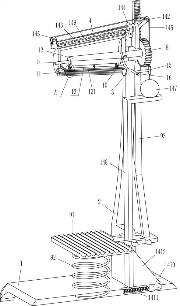
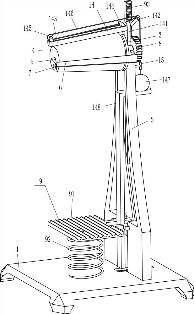
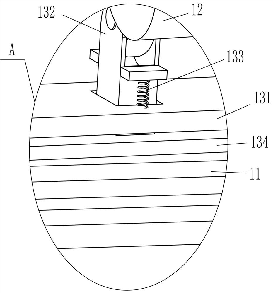
[0021] A field screw processing usa resilience to remove equipment, such as Figure 1 - Figure 3 As shown, including the base 1, the vertical plate 2, the notch ring plate 3, the cone number, the L-type rod 5, the cutter 6, the gear 8, the drive mechanism 9, the rotating shaft 10, the limit rod 11, the camshaft 12 and The pressing mechanism 13, the upper right side of the top of the base 1 is fixed to the vertical panel 2, and there is a drive mechanism 9 between the upper left side of the vertical plate 2 and the bottom seat 1, and the upper intermediate rotation of the upper intermediate rotation of the vertical plate 2 is rotating. 10 Right end The gear 8 in which the drive mechanism 9 is mounted, the gear 8 is in contact with the drive mechanism 9, and the rotary shaft 10 is fixed to the left side, and the opening of the cone 4 is opened in the middle of the bottom of the cone 5, and the opening 7 of the field screw can be placed. 7, The finite rod 11 is fixed to the front and ...

Embodiment 2

[0028] On the basis of Example 1, such as figure 1 with figure 2 As shown, there is a pirate mechanism 14, a pince member 14 includes a branch plate 141, a first wire wheel 142, a return plate 143, a push plate 144, a second wire wheel 145, a pulley 146, a steel ball 147, L. The type support rod 148, the third spring 149, the slider 1410, the fourth spring 1411 and the slope 1412, the outermost portion of the vertical plate 2 is fixed to the branch plate 141, and the plate 141 is fixed to the left side surface of the counter plate 143. The sliding type inner flipping plate 144 in the return plate 143 is in contact with the tapered cylinder 4, and the push plate 144 is also fitted to the opening 7, the push plate 144 is in the middle of the left side and the return plate 143 A third spring 149 is connected between the left side, and the upper portion of the push plate 144 is connected to the upper left side, and the second wire wheel 145 is mounted on the top of the top of the retu...

Embodiment 3

[0031] On the basis of Example 1 and Example 2, if figure 1 with figure 2 As shown, there is also a wire tube 15 and a support frame 16, and a support frame 16 is fixed between the upper and rear side surfaces of the vertical plate 2, and the support frame 16 is fixed to the wire tube 15, and the wire pipe 156 passes through the wire tube 15 Cooperate.

[0032] When the steel ball 147 is moved toward the left by the pulley 146, the wire tube 15 is guided by the wire 146, and when the operator pulls the steel ball 147 to move upward, the pulley 146 is relaxed, the wire tube 15 also performs the pulley 146. guide. As such, it is possible to avoid pulling the pulley 146 cascading to the gear 8 to affect its rotation.


PUM


Abstract

The invention relates to a removal device, in particular to a batch removal device for snail tails for processing snails. The technical problem is how to design a kind of equipment that can facilitate people to cut off the snail tails, save labor, and can cut off a plurality of snail tails at one time, and has high work efficiency. A device for removing snail tails in batches for snail processing, comprising: a base, a vertical plate is fixedly connected to one side of the base, and a rotating shaft is rotatably connected to the side away from the base. In the present invention, by putting an appropriate amount of snails into the opening, and then stepping on the pedal to move downwards, the gears can be rotated forward, and the conical cylinder can also be rotated forward. When it is in contact with the cutter, the cutter cuts off the tail of the snail. In this way, there is no need for people to hold the signature to cut off the tail of the snail, which is labor-saving and convenient to operate. It can cut off the tails of multiple snails at one time, and the work efficiency is high.

Description

Technical field [0001] The present invention relates to a removal device, and more particularly to a field removal equipment for a field screw processing field. Background technique [0002] Tian Jin's famous China Founda Skin, the freshwater lake, the reservoir, rice fields, and the pond ditch in our country are widely distributed. Because of its delicious, nutritious, and has a heat-thirst, clear and thin, and become one of the loved water products, especially the southerners use it as a cuisine, and the fields need to screw before eating. The tail resection, avoiding the toxic substances in the fields of the tail of the tail, affects the health of your health. [0003] At present, most of them are manually manually removed the tail of the field. First, people pick up a field screw, then clamp the fields, then use the force to hold the pliers, thus removing the tail of the field, but the screw housing is hard, and the hand needs The continuous grip of the pliers, the time is lo...

Claims


Application Information

Patent Timeline
Patent Type & Authority Patents(China)
IPC IPC(8): A22C29/00
CPCA22C29/00
Inventor 李芳伟
Owner 南京幸庄科技创新产业园管理有限公司
Why Eureka
Try Eureka