Air-gap-free semi-closed backflushing comprehensive arc extinguishing lightning arrester without air gap

A semi-closed, arrester technology, applied in the field of arresters, can solve the problems of poor arc extinguishing and lightning protection, poor durability, and weak arc extinguishing ability.

Pending Publication Date: 2020-10-27
王巨丰
View PDF3 Cites 1 Cited by
  • Summary
  • Abstract
  • Description
  • Claims
  • Application Information

AI Technical Summary

Problems solved by technology

[0004] The applicant and related inventors found the following problems in the existing lightning protection device during the continuous research process: 1) The arc extinguishing ability is not strong, and the arc extinguishing energy of the arc extinguishing device always affects the flashover arc energy; 2) The arc extinguishing sensitivity is not high , there is a problem that t

Method used


Image

  • Air-gap-free semi-closed backflushing comprehensive arc extinguishing lightning arrester without air gap
  • Air-gap-free semi-closed backflushing comprehensive arc extinguishing lightning arrester without air gap
  • Air-gap-free semi-closed backflushing comprehensive arc extinguishing lightning arrester without air gap

Examples


Embodiment 1

[0048] Such as Figure 2-4 As shown, a non-air gap semi-closed recoil integrated arc-extinguishing arrester includes an arrester main body 1; the upper and lower ends of the arrester main body 1 are respectively installed on the two ends of the insulator string through connecting fittings to form a reliable electrical connection; The interior of the arrester main body 1 is hollow, and an insulating partition 7 is arranged longitudinally along the arrester main body 1 so that two independent arc extinguishing chambers 10 are formed inside the arrester main body 1; The flushing device 4 has a recoil opening at the lower end; the top electrode 2 is provided at the top of the recoil device 4; a jet airflow device 5 is provided inside the lower end of the arc extinguishing chamber on the right side, and an air jet device 5 extending outward is provided at the upper end. The airflow nozzle 9; the bottom of the jet airflow device 5 is provided with a lower electrode 3; the insulating...

Embodiment 2

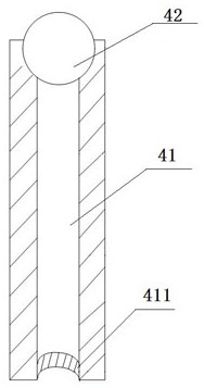
[0053] Such as Figure 5 As shown, the difference between this embodiment and Embodiment 1 is that: the opening of the recoil tube 41 is provided with an arc guide ring I 411 ; the opening of the spray tube 52 is provided with an arc guide ring II 521 . The wall electrode 6 adopts a compressed arc extinguishing tube, and the inside of the compressed arc extinguishing tube is provided with an arc guiding ball

Embodiment 3

[0055] Such as Image 6 As shown, the difference between this embodiment and Embodiment 2 is that the wall electrode 6 uses a recoil tube. The recoil pipe is a semi-closed pipe with one end open and the other end connected to the lightning pole. The outer surface of the arrester body 1 is provided with several skirts 8 .


PUM


Abstract

The invention discloses an air-gap-free semi-closed backflushing comprehensive arc extinguishing lightning arrester, which comprises a lightning arrester main body, wherein the upper end and the lowerend of the lightning arrester main body are installed at the two ends of an insulator string through connecting fittings respectively to form reliable electric connection, the lightning arrester mainbody is hollow, an insulating partition plate is arranged in the longitudinal direction of the lightning arrester main body so as to form two independent arc extinguishing cavities in the lightning arrester main body, a backflushing device is arranged in the upper end of the left arc extinguishing cavity, a backflushing opening is formed in the lower end, an upper electrode is arranged at the topend of the backflushing device, an airflow jetting device is arranged in the lower end of the arc extinguishing cavity on the right side, an airflow nozzle extending towards the outer side surface isformed in the upper end, a lower electrode is arranged at the bottom of the airflow jetting device, and a wall electrode is arranged on the insulating partition plate. The lightning arrester can effectively prevent the flashover problem of the insulator, reduces the lightning trip-out rate of power equipment, protects power facilities, improves the reliability of a power grid, and facilitates thesafe production of power.

Description

technical field [0001] The invention belongs to a lightning arrester for power transmission and distribution overhead lines, and relates to a semi-closed recoil comprehensive arc-extinguishing lightning arrester without an air gap. Background technique [0002] Lightning strikes will bring different forms of damage and damage to power facilities. Thundercloud discharge will cause lightning overvoltage in the power system. Common overvoltages in overhead lines include lightning strikes near the overhead line through electromagnetic induction on the transmission line. Voltage and lightning strike directly on the wire to generate overvoltage. Lightning strikes cause overvoltage, which may cause damage to insulators and transmission lines; lightning strikes cause flashover discharges on insulators, which will cause burns and fall off on the porcelain surface or cause network cracks on glass insulators, greatly reducing the insulation strength; lightning strikes on transmission l...

Claims


Application Information

Patent Timeline
IPC IPC(8): H01T1/02H01T1/08H01T1/10H01T4/08H01B17/48H01B17/46
CPCH01B17/46H01B17/48H01T1/02H01T1/08H01T1/10H01T4/08
Inventor 王巨丰王嬿蕾张奇星徐宇恒周勇军
Owner 王巨丰
Why Eureka
Try Eureka