
Bi-direction expansion fixed-connecting assembly device

A technology for fixing components and connecting components, applied in the direction of fixtures, mechanical equipment, etc., can solve the problem of affecting the movement of all-aluminum furniture cabinets, affecting the beauty and grade of all-aluminum furniture cabinets, affecting the firmness and reliability of aluminum alloy sheet assembly and connection, etc. question

Pending Publication Date: 2020-10-27
彭志军
View PDF0 Cites 0 Cited by
  • Summary
  • Abstract
  • Description
  • Claims
  • Application Information

AI Technical Summary

Problems solved by technology

In the practical application of this method, there are mainly some shortcomings: first, self-tapping screws are used for fixed connection, and the occlusal contact area between the self-tapping screws and the aluminum alloy material is small. When the connected aluminum alloy plate is subjected to Under the action of external force, the connection of self-tapping screws is prone to deformation and tearing, which affects the firmness and reliability of the assembly connection between aluminum alloy sheets; the second is to use self-tapping screws for fixed connection, usually one Self-tapping screws cannot be fixed, but several self-tapping screws are used for multi-point fixing, which usually leaves several screw heads on the surface of the aluminum alloy sheet, which affects the all-aluminum furniture cabinet. Third, self-tapping screws are used for fixed connection, because the same screw hole cannot be restored after being expanded once, and the same screw hole cannot be locked when it is used repeatedly, so that the all-aluminum furniture cabinet cannot be assembled and disassembled repeatedly. It greatly affects the moving of all-aluminum furniture cabinets; Fourth, after assembly, there will be a large gap between the contact surfaces between the aluminum alloy sheet and the aluminum alloy sheet, the assembly tightness is poor, and the assembly quality is not good.

Method used


Image

  • Bi-direction expansion fixed-connecting assembly device
  • Bi-direction expansion fixed-connecting assembly device
  • Bi-direction expansion fixed-connecting assembly device

Examples


Embodiment 1

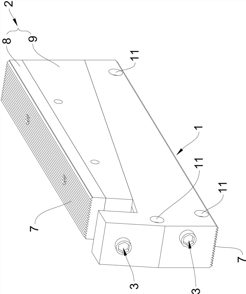
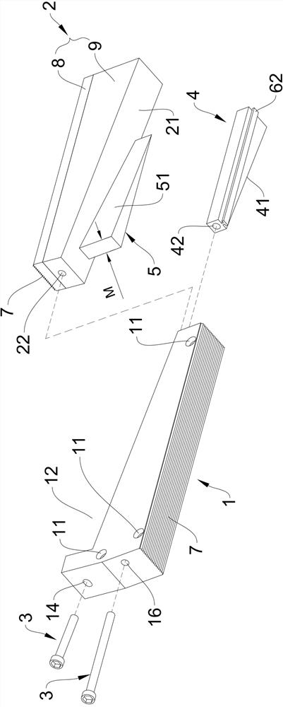
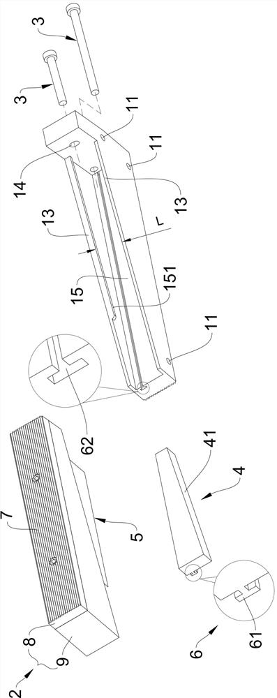
[0021] Such as Figure 1 to Figure 3 As shown, a two-way expansion-fixed connection component device according to the present invention includes a fixed component 1 , a movable component 2 and a locking bolt 3 . In order to achieve the purpose proposed by the present invention, the fixed component 1 is provided with a transverse fixing hole 11, that is, as figure 1 shown. The number of the transverse fixing holes 11 can be set according to the length of the fixed component 1 and the movable component 2 as required. The fixed component 1 and the movable component 2 are generally processed to be close to the width of the plate or workpiece to be applied. Such as Figure 9 As shown, the fixing assembly 1 is in this way, using screws 40 to fix one of the plates or the side of the workpiece.

[0022] Such as figure 2 and image 3 As shown, the fixed assembly 1 is also provided with a storage recess 12 for the movable assembly 2 to be stored, and a first fitting slope 13 is a...

Embodiment 2

[0029] The difference between the second embodiment and the first embodiment is that the first embodiment adopts the fitting strip 4 as the component that generates the lateral movement of the pressing movable assembly 2, thereby eliminating the problem of the gap between workpieces. In the second embodiment, the joint bar 4 is eliminated, and two sets of joint slopes and one set of joint side slopes are used to realize the lateral movement of the compressing movable assembly 2, thereby eliminating the gap problem between workpieces. The principles and effects of other aspects are basically the same as those of the first embodiment. The technical scheme of the second embodiment is specifically as follows: Figure 5 As shown, it includes a fixed assembly 1, a movable assembly 2 and a locking bolt 3 and the like. In order to achieve the purpose proposed by the present invention, the fixed component 1 is provided with a transverse fixing hole 11, that is, as figure 1 shown. Th...


PUM


Abstract

The invention relates to a bi-direction expansion fixed-connecting assembly device. The bi-direction expansion fixed-connecting assembly device comprises a fixed assembly, a movable assembly and locking bolts. A hidden-arranged concave position and a first matching inclined plane are further arranged on the fixed assembly. The movable assembly is further provided with a second matching inclined plane. A first screw hole and a first through hole are formed respectively in the movable assembly and the fixed assembly. One locking bolt penetrates from the first through hole and is locked into thefirst screw hole, and the locking bolt is swirled so that longitudinal expansion tensioning strength is generated by the movable assembly and the fixed assembly. A groove is further formed in the first matching inclined plane. A matching strip with a first matching side inclined plane is installed in the groove. A convex strip portion with a second matching side inclined plane is further arrangedon the second matching inclined plane. The second matching side inclined plane matches with the first matching side inclined plane. A second screw hole and a second through hole are formed respectively in the matching strip and the fixed assembly. The other locking bolt penetrates from the second through hole and is locked into the second screw hole, the locking bolt is swirled so that the movableassembly is pressed by the matching strip and transverse tensioning strength is generated.

Description

technical field [0001] The invention relates to the technical field of accessories for fixed connection between workpieces, in particular to an accessory mechanism that uses expansion force to realize fixed connection between two workpieces. Background technique [0002] In the assembly and fixed connection between the existing workpieces, the most commonly used method is to fix the connection with self-tapping screws. For example, in the assembly of all-aluminum furniture cabinets, when the aluminum alloy plates are fixedly connected with the aluminum alloy plates, an aluminum alloy square bar is usually fixed on the side of one of the aluminum alloy plates with self-tapping screws; There is a groove on the end surface of an aluminum alloy plate, which is nested on the aluminum alloy square bar, and then locked into the aluminum alloy square bar with self-tapping screws from the outside of the groove to realize the gap between the two aluminum alloy plates. vertical assemb...

Claims


Application Information

Patent Timeline
Patent Type & Authority Applications(China)
IPC IPC(8): F16B1/00
CPCF16B1/00
Inventor 彭志军
Owner 彭志军
Learn More