
Box container plastic uptake mould capable of conveniently de-moulding

A blister mold and demoulding technology, which is applied to household appliances, other household appliances, household components, etc., can solve the problems of high demoulding force, inability to demould, and rupture of the box.

Inactive Publication Date: 2020-10-27
滁州新佳诚模具制造有限公司
View PDF7 Cites 4 Cited by
  • Summary
  • Abstract
  • Description
  • Claims
  • Application Information

AI Technical Summary

Problems solved by technology

[0005] Aiming at the deficiencies in the prior art, the present invention provides a tank plastic mold that is convenient for demoulding, which solves the problem that most of the existing plastic molds are ejected by the power of the top plate during the demoulding process. Sticky, it is easy to cause the tank to break due to excessive demoulding force, and most of the tank plastic molds are cooled and demoulded by air cooling or water cooling alone during production. The cooling molding speed is slow, which affects production efficiency and will cause demoulding It is easy to have the problem of not being able to demould or causing damage to the blister product

Method used


Image

  • Box container plastic uptake mould capable of conveniently de-moulding
  • Box container plastic uptake mould capable of conveniently de-moulding
  • Box container plastic uptake mould capable of conveniently de-moulding

Examples

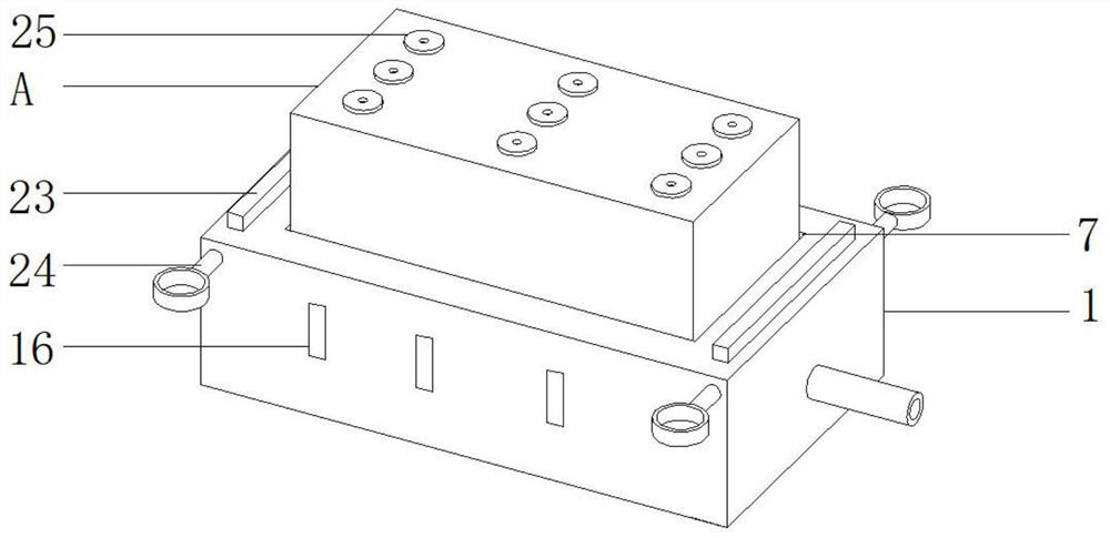
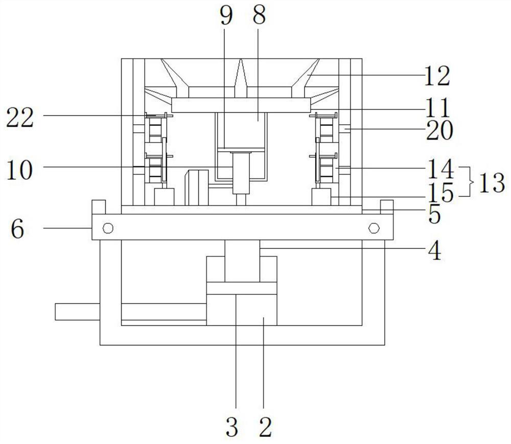
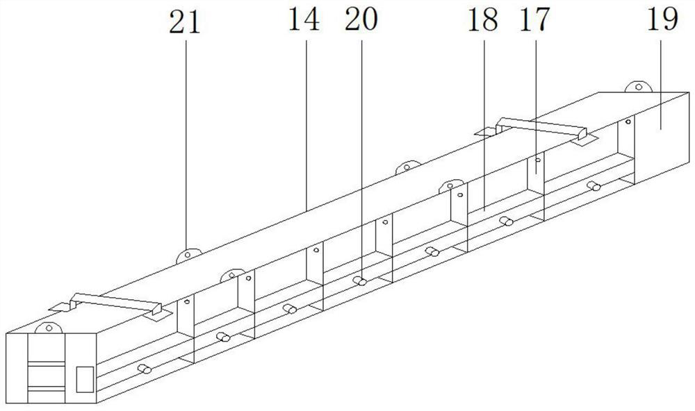

Embodiment Construction

[0025] The following will clearly and completely describe the technical solutions in the embodiments of the present invention with reference to the accompanying drawings in the embodiments of the present invention. Obviously, the described embodiments are only some, not all, embodiments of the present invention. Based on the embodiments of the present invention, all other embodiments obtained by persons of ordinary skill in the art without making creative efforts belong to the protection scope of the present invention.

[0026] see Figure 1-3 , the embodiment of the present invention provides a technical solution: a convenient demoulding box tank blister mold, including a power frame 1 and a mold A arranged on the top of the power frame 1. A storage cavity is provided in the middle of the interior of the power frame 1 and the central position is An oil cylinder 2 is provided, and a movable sealing plug 3 is arranged inside the oil cylinder 2, and the left side of the oil cyli...


PUM


Abstract

The invention discloses a box container plastic uptake mould capable of conveniently de-moulding. The box container plastic uptake mould capable of conveniently de-moulding comprises a power frame anda mould arranged on the top of the power frame, wherein the middle part inside the power frame is provided with a storage cavity, and the center position of the power frame is provided with an oil cylinder; a movable sealing plug is arranged inside the oil cylinder; the left side of the oil cylinder horizontally communicates with an oil passing tube; a movable load-bearing column is connected above the sealing plug; the bottom end of the mould is welded with a stainless steel cushion plate which is connected to the load-bearing column; the middle of the cushion plate on the top of the power frame is provided with a slot hole which corresponds to the mould; the cushion plate and the mould on the top of the cushion plate can move up and down; and the mould comprises a top plate and side plates formed by side corners of the top plate. The mould is controlled to move, so that an external workpiece is in contact and extrusion with the power frame on the bottom, and therefore, de-moulding is promoted; and a column hole can be additionally formed in the top plate of the mould for exhausting gas outwards; and cooling structures on inner walls of the side plates of the mould can quicken cooling and assist de-moulding, so that de-moulding efficiency is high.

Description

technical field [0001] The invention relates to the technical field of mold equipment, in particular to a box tank blister mold for easy demoulding. Background technique [0002] Blister mold refers to the mold used in the production of blister. The lowest cost is the plaster mold, followed by the electroplating copper mold, and the most expensive is the aluminum mold. The mold is drilled with small holes, which are used for vacuum adsorption of thermalized hard film to form blister products. [0003] During the demoulding process of the existing blister molds, most of them are ejected by the power of the top plate. Due to the stickiness of the side wall of the tank, it is easy to cause the tank to break due to excessive demoulding force, and most of the tank blister molds are produced during production. Air-cooling or water-cooling is used alone for cooling and demolding, the cooling molding speed is slow, which affects production efficiency, and it is easy to fail to demo...

Claims


Application Information

Patent Timeline
IPC IPC(8): B29C51/30B29C51/40B29C51/42B29C51/44B29C33/04B29L31/00
CPCB29C51/303B29C51/40B29C51/428B29C51/44B29L2031/712
Inventor 张继发
Owner 滁州新佳诚模具制造有限公司
Learn More