Split type sliding block structure under stroke limit

A technology of stroke limitation and slider, which is applied in the field of split slider structure, can solve the problems of small core-pulling space and unable to complete manual core-pulling

Active Publication Date: 2020-10-27
NINGBO JOYSONQUIN AUTOMOTIVE SYST HLDG CO LTD
View PDF6 Cites 2 Cited by
  • Summary
  • Abstract
  • Description
  • Claims
  • Application Information

AI Technical Summary

Problems solved by technology

[0005] Aiming at the technical problem that the core-pulling space in the prior art is too small to complete the manual core-pulling, the present invention provides a split slider structure under stroke limitation, which can realize automatic core-pulling in a limited mold space, and solves the problem of The dilemma of needing to manually take out and place the slider, but also avoids the risk of slider damage caused by manual operation

Method used


Image

  • Split type sliding block structure under stroke limit
  • Split type sliding block structure under stroke limit
  • Split type sliding block structure under stroke limit

Examples


Embodiment 1

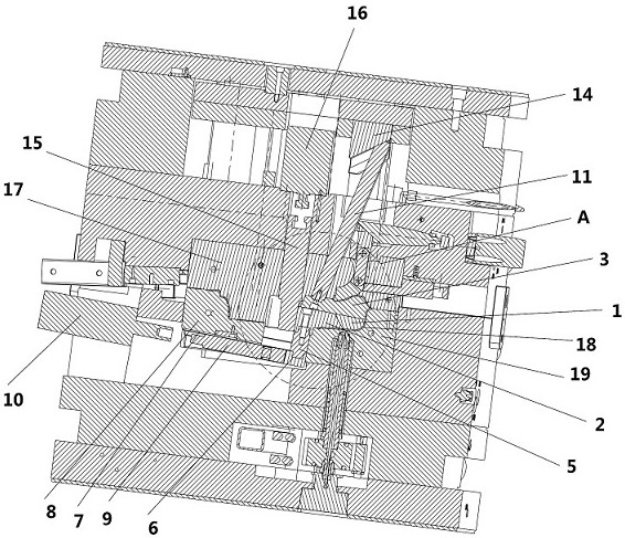
[0044] combined with Figure 1-14 , a split slider structure under stroke limitation in this embodiment, including a slider head 1, a slider 2, an inclined head 3, a slider connecting seat 5, a front mold slider seat 6, a driving connecting rod 9, a A driving member 10, inclined ejector rod 11, inclined ejector seat 14, wedging block 15 and second driving member 16, the slider head 1 and the slider 2 are slidably connected by the second dovetail groove 21, and the slider head 1 and the slider 2 are slidingly connected with the inclined head 3 through the first dovetail groove 20, one end of the slider connecting seat 5 is fixedly connected with the slider 2, and the other end of the slider connecting seat 5 is connected with one end of the front mold slider seat 6 Fixedly connected, the other end of the front mold slider seat 6 is fixedly connected with one end of the driving connecting rod 9, the other end of the driving connecting rod 9 is fixedly connected with the first dr...

Embodiment 2

[0047] combined with Figure 11 and 12 , a split slider structure under stroke limitation in this embodiment, compared with the technical solution of Embodiment 1, further includes a limit clamp 4, the limit clamp 4 includes a protrusion 41 and a groove 42, the The protrusion 41 is provided on the side where the slider head 1 is connected to the slanting head 3 or the side where the slanting head 3 is connected to the slider 2 and the slider head 1, and the groove 42 is located on the side where the slanting head 3 is connected to the slider 2 and The side where the slider head 1 is connected or the side where the slider head 1 is connected to the inclined head 3 .

[0048] There are four identical grooves 42 or protrusions 41 arranged on the side of the inclined plug 3 connected with the slider 2 and the slider head 1 , which are evenly arranged at both ends of the inclined plug 3 . Two identical protrusions 41 or grooves 42 are provided on the side where the slider head 1 ...

Embodiment 3

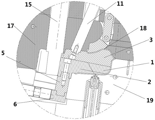
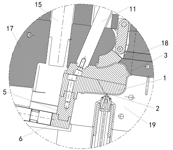
[0050] combined with Figure 10-12 , a split slider structure under stroke limitation in this embodiment, compared with the technical solution of Embodiment 1 or 2, the side of the inclined head 3 connected to the slider 2 and the slider head 1 is provided with the first A dovetail groove 20 matches the rib 31 .

[0051] The shape of the dovetail groove is ∠, and the convex strip 31 matches the first dovetail groove 20 and can slide in the first dovetail groove 20 without falling out. During the first core-pulling process and the second core-pulling process, the first dovetail groove 20 acts as a guide, and the convex strip 31 slides in the first dovetail groove 20 . During the third core-pulling process, the first dovetail groove 20 acts as a fixed connection, and due to the fixing effect of the limit clip 4, the convex strip 31 will not slide in the first dovetail groove 20, so that the slider head 1 follows the inclined head. 3 Do ejection exercise.


PUM


Abstract

The invention discloses a split type sliding block structure under a stroke limit, and belongs to the technical field of injection molds. The split type sliding block structure comprises a sliding block head, a sliding block, an oblique top head, a sliding block connecting seat, a front mold sliding block seat, a driving connecting rod, a first driving part, an oblique top rod, an oblique top seat, a wedge tightening block and a second driving part, wherein the sliding block head and the sliding block are slidably connected with the inclined top head through a first dovetail groove, one end ofthe sliding block connecting seat is fixedly connected with the sliding block, the other end of the sliding block connecting seat is fixedly connected with one end of the front mold sliding block seat, the other end of the front mold sliding block seat is fixedly connected with one end of the driving connecting rod, and the other end of the driving connecting rod is fixedly connected with the first driving part. For the problems that because a core pulling space is too small in the prior art, the manual core pulling cannot be completed, the split type sliding block structure can realize automatic core pulling in a limited mold space, solves the problem that the sliding block needs to be manually taken out and placed, and also avoids the risk that the sliding block is prone to being damaged caused by manual operation.

Description

technical field [0001] The invention relates to the technical field of injection molds, in particular to a split slider structure under stroke limitation. Background technique [0002] In the prior art, during injection molding, the slide block is manually placed on the moving mold core, and then the molds are closed for injection molding. After the injection molding is completed, the product is ejected together with the sliders, and then the workers manually take out the sliders one by one, and then place the sliders on the moving mold core for the injection molding of the next mold. [0003] Some injection molding products have the feature of undercut. When the depth of the undercut area is relatively large and the core-pulling space is too small, it is difficult to manually remove and place the slider. Manually taking out and placing the slider greatly prolongs the product production cycle and increases the product production cost. At the same time, the slider is easily...

Claims


Application Information

Patent Timeline
IPC IPC(8): B29C45/26B29C45/33B29C45/44
CPCB29C45/2602B29C45/33B29C45/332B29C45/4435
Inventor 郑海笑王龙胜
Owner NINGBO JOYSONQUIN AUTOMOTIVE SYST HLDG CO LTD
Why Eureka
Try Eureka