
Working table for electronic equipment production and processing

A technology for electronic equipment and workbenches, applied in workbenches, mechanical equipment, lighting and heating equipment, etc., can solve the problems of small electronic parts, affecting work efficiency, and inconvenient operation.

Inactive Publication Date: 2020-10-27
李赵和
View PDF0 Cites 1 Cited by
  • Summary
  • Abstract
  • Description
  • Claims
  • Application Information

AI Technical Summary

Problems solved by technology

Electronic equipment needs to use a workbench for processing and assembly during production, but when the existing workbench for electronic equipment production and processing is used, especially for processing small electronic equipment, it is inconvenient to operate during the production and processing process, and the light in the working environment Strength also often affects work efficiency. This is because electronic parts are often relatively small, and the precision requirements for production and processing are high. This requires production personnel to operate carefully during the operation process. In practice, production is often set in a workshop with more light , but this will still receive the image of factors such as its own light and shadow, resulting in lower production efficiency

Method used

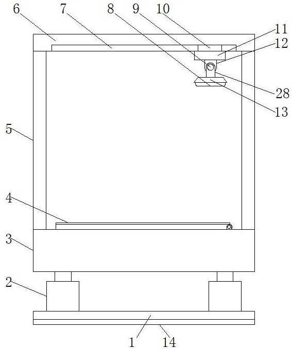

Image

  • Working table for electronic equipment production and processing
  • Working table for electronic equipment production and processing
  • Working table for electronic equipment production and processing

Examples


Embodiment Construction

[0022] The following will clearly and completely describe the technical solutions in the embodiments of the present invention with reference to the drawings in the embodiments of the present invention.

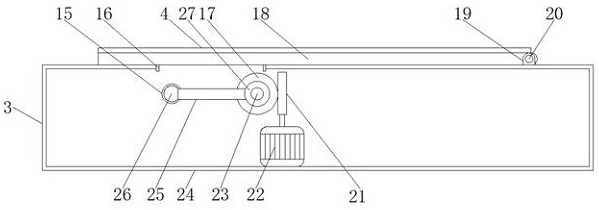
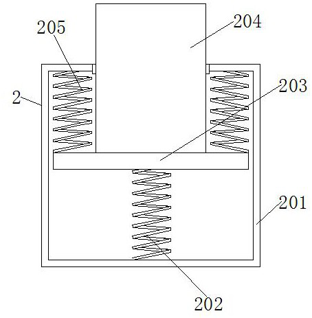
[0023] An embodiment of the present invention provides a workbench for production and processing of electronic equipment, such as Figure 1-3 As shown, including the base 1, the bottom of the base 1 is fixedly connected with an anti-skid pad 14, and the bottom of the anti-skid pad 14 is provided with anti-skid lines, and both sides of the top of the base 1 are fixedly connected with a shock absorber 2, and the top of the shock absorber 2 is connected to There is a workbench body 3, the top of the workbench body 3 is provided with a worktable 4, the top of the workbench body 3 and both sides of the workbench 4 are fixedly connected with support columns 5, and the top of the support column 5 is fixedly connected with a top plate 6 The lampshade 13 is arranged under the top plate...


PUM


Abstract

The invention provides a working table for electronic equipment production and processing, and relates to the field of electronic equipment. The working table for electronic equipment production and processing comprises a base, wherein a non-slip mat is fixedly connected to the bottom part of the base; non-slip lines are arranged on the bottom part of the non-slip mat; damping devices are fixedlyconnected to two sides of the top part of the base; a working table body is connected to the top parts of the damping devices; a working table board is arranged on the top part of the working table body; support pillars are fixedly connected to the positions, located on two sides of the working table board, on the top part of the working table body; and a top plate is fixedly connected to the topparts of the support pillars. According to the working table for electronic equipment production and processing, a lampshade is rotated manually, an angle of the lampshade can be conveniently adjustedthrough the mutual matching of a first installation block, a second installation block and a first hinged piece, and an illuminating angle is conveniently adjusted, so that a shaded area is reduced,an illuminating effect is better, a workpiece can be conveniently processed, and the production efficiency is effectively improved.

Description

technical field [0001] The invention relates to the technical field of electronic equipment, in particular to a workbench for production and processing of electronic equipment. Background technique [0002] Electronic equipment refers to equipment that is composed of electronic components such as integrated circuits, transistors, and electron tubes, and uses electronic technology software to play a role, including electronic computers, robots controlled by electronic computers, numerical control or program-controlled systems, etc. Electronic equipment in the classification of fixed assets mainly includes: computers, air conditioners, refrigerators, washing machines, microwave ovens, printers, fax machines and all-in-one machines, etc. Electronic equipment needs to use a workbench for processing and assembly in production, but when the existing workbench for electronic equipment production and processing is used, especially for processing small electronic equipment, it is inc...

Claims


Application Information

Patent Timeline
IPC IPC(8): B25H1/02B25H1/16F21V33/00F16F15/067
CPCB25H1/02B25H1/16F16F15/067F21V33/00
Inventor 李赵和
Owner 李赵和
Learn More