
Fire extinguishing system based on fire monitor group and fire extinguishing method

A technology of fire extinguishing system and fire monitor, which is applied in the field of fire extinguishing system based on fire monitor groups, and can solve the problems of high reconstruction cost, difficult data processing, and large amount of data calculation

Inactive Publication Date: 2020-10-27
HEFEI KDLIAN SAFETY TECHNOLOGY CO LTD
View PDF8 Cites 3 Cited by
  • Summary
  • Abstract
  • Description
  • Claims
  • Application Information

AI Technical Summary

Problems solved by technology

That is to say, a method for spatially locating the same fire source through multiple positioning modules is disclosed, but the main body used is on a fire-fighting robot. When assembling, a corresponding number of positioning modules such as infrared cameras can be set as required. For the fire monitors of the fixed fire protection system, each fire monitor is equipped with only one positioning module. Using the binocular positioning method needs to upgrade the entire fire protection system, and because the fixed positions of the fire monitors are different, the relative distance between the fire monitor and the positioning module The heights are different, and each fire monitor needs to be configured with separate control parameters, and when using an infrared camera to determine the distance and orientation of the fire source, it is necessary to use the parameters obtained by the camera itself to participate in the calculation, and the amount of data calculation is large
Therefore, when this method is applied to existing fire monitors, there are problems such as high modification cost and difficult data processing.

Method used


Image

  • Fire extinguishing system based on fire monitor group and fire extinguishing method
  • Fire extinguishing system based on fire monitor group and fire extinguishing method
  • Fire extinguishing system based on fire monitor group and fire extinguishing method

Examples


Embodiment Construction

[0047] In order to make the object, technical solution and advantages of the present invention clearer, the present invention will be further described in detail below in conjunction with specific embodiments and with reference to the accompanying drawings.

[0048] This embodiment also provides a fire extinguishing system based on fire monitor groups, including a water supply system, a plurality of fire monitors communicated with the water supply system and a controller for controlling the work of the fire monitors, the fire monitors include an image positioning component, and the control The controller locates the fire source in space based on the image positioning component, and controls the fire monitor to extinguish the fire. The controller is also communicatively connected with an alarm module, and the controller sends the fire video, sound and alarm information to the alarm module for display and playback.

[0049] The fire monitor includes a decoder, an image positioni...


PUM


Abstract

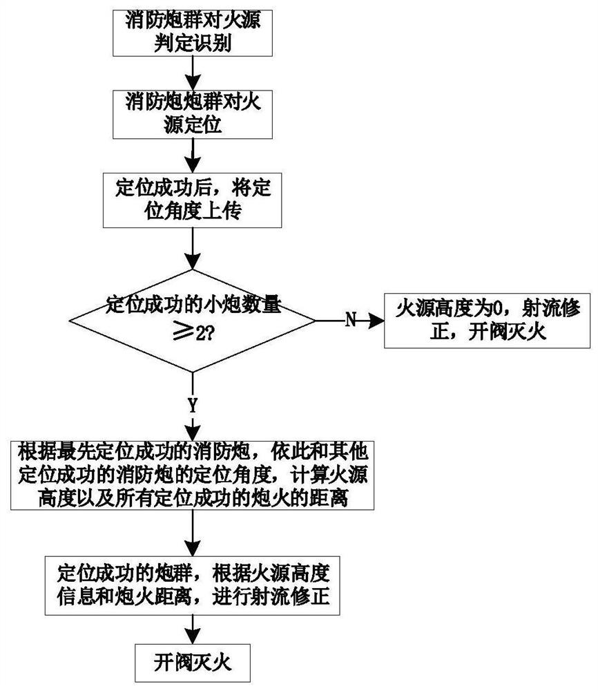
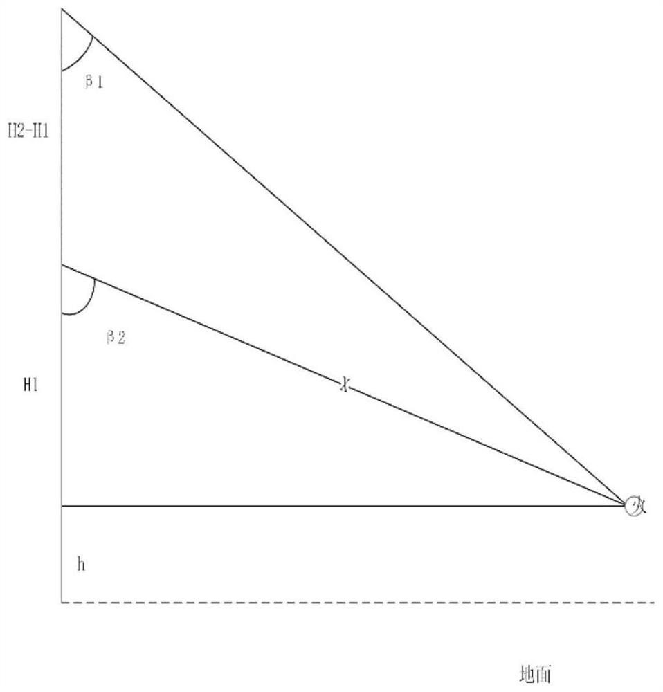
The invention provides a fire extinguishing system based on a fire monitor group. The fire extinguishing system based on the fire monitor group comprises a water supply system, a plurality of fire monitors communicating with the water supply system and a controller for controlling the fire monitors to work, each fire monitor comprises an image positioning assembly, and the controller carrying outpositioning on a fire source based on the image positioning assembly, and controls the fire monitors to extinguish fire at the fire source position. The invention further provides a fire extinguishingmethod based on the fire extinguishing system, positioning is carried out on the fire source according to the angles of the fire monitors, the jet flow parabola parameters of the fire monitors are calculated based on the positioning result, and the fire monitors are controlled to extinguish the fire through the jet flow parabola parameters. The fire extinguishing system based on the fire monitorgroup and the fire extinguishing method have the advantages that under the condition that the fire monitor group is erected, active monitoring and automatic positioning of the fire source can be achieved, fire extinguishing is rapidly and efficiently carried out on a target space, and the safety is improved.

Description

technical field [0001] The invention relates to the technical field of fire extinguishing, in particular to a fire extinguishing system and a fire extinguishing method based on a group of fire monitors. Background technique [0002] With the gradual increase of people's attention to fire safety issues, highly intelligent fire protection products are widely used, and higher requirements are also put forward for the detection accuracy and fire extinguishing accuracy of fire protection products. Existing fire-fighting systems that use fire monitors to extinguish fires generally use a single fire monitor to locate the fire source, and scan the fire source by rotating the camera fixed on the top of the intelligent fire monitor barrel. When the flame is located at the imaging center point, the positioning is realized . However, due to the lack of information on the height of the fire source, the spatial position of the fire source cannot be confirmed, resulting in low accuracy of...

Claims


Application Information

Patent Timeline
IPC IPC(8): A62C37/00A62C31/00
CPCA62C31/00A62C37/00
Inventor 石晓龙徐云绯许玉坤金卫东周扬巢佰崇张克年杨广
Owner HEFEI KDLIAN SAFETY TECHNOLOGY CO LTD
Learn More