
Automatic focusing method and system based on flight time

An autofocus and time-of-flight technology, which is applied in the parts of TV systems, parts of color TVs, TVs, etc., can solve the problems of interference between light and scene changes, difficulty, and damage to the correlation of eigenvalues.

Inactive Publication Date: 2020-10-23
深圳市中江天华科技有限公司
View PDF6 Cites 0 Cited by
  • Summary
  • Abstract
  • Description
  • Claims
  • Application Information

AI Technical Summary

Problems solved by technology

[0002] With the continuous upgrading of the imaging system, the camera technology in various scenarios is also being updated. Focusing is a relatively basic requirement of the imaging system, but if it is more robust, it is quite difficult; in real-time focusing, the image will be affected by light. Interference with scene changes; when there are fast-moving or changing objects inside the scene, the eigenvalue correlation of the multi-frame images on which the focus depends is destroyed
[0003] In the prior art, in low-light and low-light environments, visible light is absorbed by the environment, and the signal received by the photosensitive part of the imaging system is already weak. At the same time, the noise generated by the imaging system seriously affects the imaging quality of the equipment, resulting in blurred images; currently supports from 50 - The focusing method of the imaging range between 3000 meters is not mature, it is difficult or even impossible to deal with the super long-distance focusing situation

Method used


Image

  • Automatic focusing method and system based on flight time
  • Automatic focusing method and system based on flight time
  • Automatic focusing method and system based on flight time

Examples


Embodiment Construction

[0024] Reference will now be made in detail to the exemplary embodiments, examples of which are illustrated in the accompanying drawings. When the following description refers to the accompanying drawings, the same numerals in different drawings refer to the same or similar elements unless otherwise indicated. The implementations described in the following exemplary examples do not represent all implementations consistent with this disclosure. Rather, they are merely examples of apparatuses and methods consistent with aspects of the presently disclosed embodiments as recited in the appended claims.

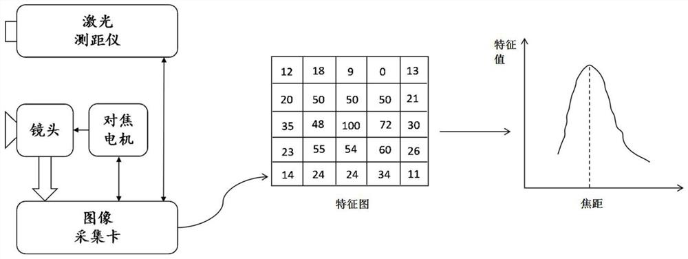
[0025] see figure 1 , in an embodiment of the present invention, a time-of-flight based autofocus method, comprising the following steps:

[0026] S21. Measure the object distance u from the target object through the laser ranging module, and send the object distance data to the image acquisition card;

[0027] S22. The image acquisition card calculates the initial focal length...


PUM


Abstract

The invention relates to the technical field of imaging systems, in particular to an automatic focusing method and system based on flight time, and the method comprises the following steps: measuringan object distance u between a laser ranging module and a target object, and transmitting object distance data to an image acquisition card; enabling the image acquisition card to estimate an initialfocal length f of the lens through interpolation operation by taking an object distance u as a setting basis; enabling the image acquisition card to set a focusing search range and a focusing motor motion step number according to a focal length f, obtain a plurality of images in the focusing search range, compare the obtained images to obtain a maximum characteristic value, and record an adjustment value of the focusing motor when the maximum characteristic value is obtained; and adding the adjustment value and the initial focal length to obtain the focusing focal length of the lens. The method and the system have the beneficial effects that the focusing precision and stability of the lens under the condition of image movement or insufficient light are improved, the focusing range of the lens is expanded, and the lens is suitable for ultra-long-distance focusing.

Description

technical field [0001] The invention relates to the technical field of imaging systems, in particular to an automatic focusing method and system based on time-of-flight. Background technique [0002] With the continuous upgrading of the imaging system, the camera technology in various scenarios is also being updated. Focusing is a relatively basic requirement of the imaging system, but if it is more robust, it is quite difficult; in real-time focusing, the image will be affected by light. Interference with scene changes; when there are fast-moving or changing objects inside the scene, the feature value correlation of multiple frames of images on which the focus depends is destroyed. [0003] In the existing technology, in low-light and low-light environments, visible light is absorbed by the environment, and the signal received by the photosensitive part of the imaging system is already weak. At the same time, the noise generated by the imaging system seriously affects the i...

Claims


Application Information

Patent Timeline
IPC IPC(8): H04N5/232
CPCH04N23/671H04N23/67
Inventor 邓羿
Owner 深圳市中江天华科技有限公司
Learn More