Eureka AIR delivers breakthrough ideas for toughest innovation challenges, trusted by R&D personnel around the world.

In-vehicle structure of power control device

A technology of power control and structure, applied in the direction of electromechanical devices, electric vehicles, control drives, etc., can solve problems affecting the performance of the shell, unfavorable power control device connection lines and connector arrangement, etc.

Inactive Publication Date: 2020-10-23
张凤珍
View PDF1 Cites 0 Cited by
  • Summary
  • Abstract
  • Description
  • Claims
  • Application Information

AI Technical Summary

Problems solved by technology

[0002] Electric vehicles are usually equipped with a power control device that can control the power of the drive motor. In the known prior art, there is an electric vehicle that fixes the power control device on the motor housing, such as a power control device proposed by Chinese Patent Publication No. CN109808477A. The vehicle-mounted structure of the control device, published on May 28, 2019, introduces an electric vehicle in which the power control device is fixed on the motor casing, and a Bolts, but the shell of the electric control device and the shell of the motor are fixed together through the front of the bolt, which may require modification on the shells of the two devices, which will affect the performance of the shell, and the gap between the two devices due to the bolt As a result, the side walls on one side will be pressed against each other, and some bolt heads will be exposed when the bolts are installed vertically, which is not conducive to the arrangement of the connecting wires and connectors of the power control device.

Method used


Image

  • In-vehicle structure of power control device
  • In-vehicle structure of power control device
  • In-vehicle structure of power control device

Examples


Embodiment Construction

[0032] The technical solutions in the embodiments of the present invention will be clearly and completely described below in conjunction with the accompanying drawings in the embodiments of the present invention. Obviously, the described embodiments are only a part of the embodiments of the present invention, rather than all the embodiments.

[0033] In the description of the present invention, it should be understood that the terms "upper", "lower", "front", "rear", "left", "right", "top", "bottom", "inner", " The orientation or positional relationship indicated by "outside" is based on the orientation or positional relationship shown in the drawings, and is only for the convenience of describing the present invention and simplifying the description, and does not indicate or imply that the device or element referred to must have a specific orientation to The specific azimuth structure and operation cannot be understood as a limitation of the present invention.

[0034] Reference ...


PUM


Abstract

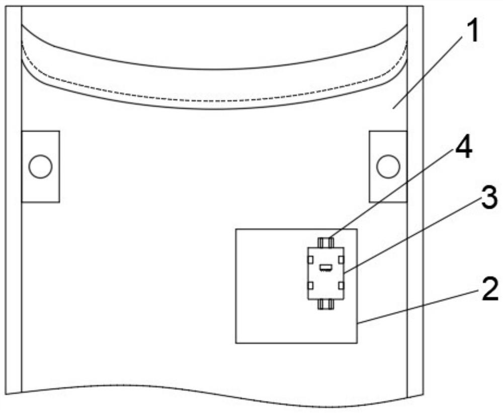
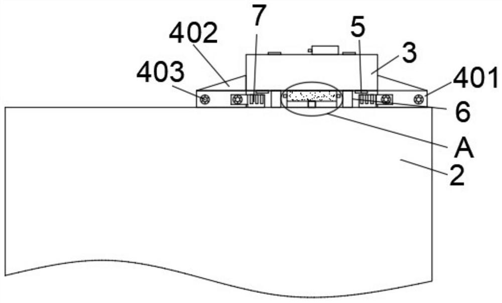
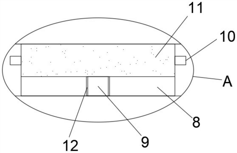
The invention discloses a vehicle-mounted structure of a power control device. The invention relates to the technical field of circuit control equipment installation. A driving motor is mounted on a machine body; a power control device is arranged in the side wall of the upper side of the driving motor shell; a connector is arranged in the lower side of the power control device; fixing mechanismsare symmetrically arranged on the side wall of the drive motor shell. Connecting mechanisms matched with the fixing mechanisms are symmetrically arranged on the side walls of the two sides of the power control device. Each fixing structure comprises a fixing plate; the fixing plate is connected to a shell of the driving motor in a welding manner, slots are symmetrically arranged in the sidewalls of the fixing plate, and threaded holes are symmetrically formed in the sidewalls of the end surfaces of the fixing plate. According to the vehicle-mounted structure of the electric power control device, excellent performance of the device shell is guaranteed, and meanwhile, interference of a bolt head used for connection to a connecting wire and a connector can be reduced.

Description

Technical field [0001] The present invention relates to the technical field of circuit control equipment installation, and in particular to a vehicle-mounted structure of a power control device. Background technique [0002] An electric vehicle is usually equipped with a power control device that can control the power of the driving motor. In the prior art, there is an electric vehicle in which the power control device is fixed on the housing of the motor. For example, the Chinese Patent Publication No. CN109808477A proposes an electric power The on-board structure of the control device was published on May 28, 2019. It introduced an electric vehicle in which the power control device was fixed to the motor housing, and the power control device mounted on the electric vehicle was installed in the housing position Bolts, but the housing of the power control device and the housing of the motor are fixed together through the front of the bolts. This may require modification on the ho...

Claims


Application Information

Patent Timeline
IPC IPC(8): H02K5/00H02K7/00H02K11/30H02K9/00F16F15/067B60R16/02B60L15/20
CPCB60L15/20B60R16/0215F16F15/067H02K5/00H02K7/006H02K9/00H02K11/30Y02T10/64Y02T10/72
Inventor 张凤珍
Owner 张凤珍
Why Eureka
Eureka Blog
Learn More