
Online sealing detection device and method

A detection device and detection method technology, which can be applied in the direction of using liquid/vacuum degree for liquid tightness measurement, by measuring the increase and deceleration rate of fluid, etc., which can solve the problem of lack of online detection method and device for tightness.

Pending Publication Date: 2020-10-23
新阳硅密(上海)半导体技术有限公司
View PDF0 Cites 0 Cited by
  • Summary
  • Abstract
  • Description
  • Claims
  • Application Information

AI Technical Summary

Problems solved by technology

[0004] The technical problem to be solved by the present invention is to provide an online leak detection device and method for overcoming the lack of an online, timely and effective leak detection method and device for components requiring single-sided sealing in the prior art , the present invention can realize the function of online, continuous, real-time, timely and effective detection of the airtightness of single-sided sealed components (such as wafers), and avoid the failure of components due to poor sealing and cannot be detected online in time. The waste and loss caused, especially the delayed measurement often loses a lot

Method used


Image

  • Online sealing detection device and method
  • Online sealing detection device and method
  • Online sealing detection device and method

Examples


Embodiment 1

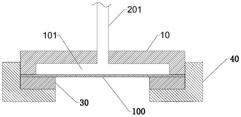
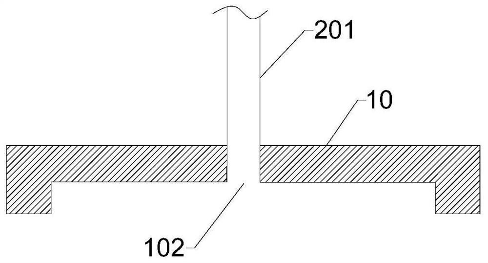
[0053] Such as Figure 1~2 As shown, the present embodiment provides a sealing on-line detection device for detecting the sealing of the element under test 100, which includes: a cover plate 10, a measuring device and a seal 30, and the element under test 100 is arranged on the cover plate 10 and seal 30;

[0054] The cover plate 10 is arranged on the upper surface of the component under test 100, and the cover plate 10 is provided with a groove, and the groove and the component under test 100 form a cavity 101; those skilled in the art can determine the size of the groove in the cover plate 10 according to the actual situation. Shape and size, for example, a cylindrical or nearly cylindrical cavity 101 is formed in this embodiment. Specifically, the cavity 101 has a diameter of 80 mm and a height of 1.6 mm, and the cavity 101 is coaxial with the device under test 100 . The size of the cylinder can be determined by those skilled in the art according to the actual situation, f...

Embodiment 2

[0068] This embodiment provides an on-line airtightness detection device. Compared with embodiment 1, the on-line airtightness detection device uses a first gas flow meter to replace the first air pressure gauge in embodiment 1, and a second gas flow meter to replace the implementation In the second barometer of Example 1, the measuring device detects the gas flow rate of the cavity 101 . All the other parts are the same as in Example 1.

Embodiment 3

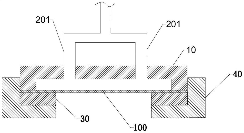
[0070] Such as image 3 As shown, this embodiment provides an on-line airtightness detection device. Compared with Embodiment 1, there are two air inlets 102 of the on-line airtightness detection device, and correspondingly, there are two gas passages 201, two The gas channel 201 is finally merged into one main gas channel 202 to reduce the number of channels, and the gas is supplied by the same gas supply source. The first air pressure gauge and the second air pressure gauge are all arranged on the merged main gas channel 202, and the remaining components are the same as Example 1 is the same.


PUM

PropertyMeasurementUnit
Outer diameteraaaaaaaaaa
The inside diameter ofaaaaaaaaaa
Heightaaaaaaaaaa

Abstract

The invention discloses an online sealing detection device and method. The online sealing detection device is used for detecting sealing performance of a to-be-detected element and comprises a cover plate, a measuring device and a sealing piece, and the to-be-detected element is arranged between the cover plate and the sealing piece; the cover plate is arranged on the upper surface of the to-be-detected element, the cover plate is provided with a groove, and the groove and the to-be-detected element form a cavity; the cover plate is provided with at least one air inlet, and the air inlet is connected with the cavity; the measuring device is connected with the air inlet through an air channel and is used for detecting the air pressure or an air flow of the cavity; and the sealing piece is arranged at the edge of the lower surface of the to-be-detected element. The device and the method can effectively detect the sealing performance of the single-side sealed element, and avoid the wasteand loss of the element caused by untight sealing, and the method is simple, convenient and effective.

Description

technical field [0001] The invention relates to an on-line leak detection device and method. Background technique [0002] In the field of semiconductor wafer electroplating, the cathode sealing effect of electroplating equipment has a great influence on the electroplating effect. In wafer electroplating, the wafer is used as the cathode of electroplating, one side is electroplated, and the other side needs to be sealed to prevent contact with the electroplating solution. [0003] In the prior art, there are many structures and designs of wafer electroplating seals (such as gaskets, etc.), but there is no detection component for the sealing effect. Therefore, in wafer electroplating production, if there is a problem with the sealing effect, the method of replacing or repairing the sealing component is generally adopted. Due to the lack of detection and early warning devices for sealing effects, the problems of wafer waste and capacity loss caused by poor sealing in wafer e...

Claims


Application Information

Patent Timeline
IPC IPC(8): G01M3/26
CPCG01M3/26
Inventor 史蒂文·贺·汪
Owner 新阳硅密(上海)半导体技术有限公司
Learn More