
Shock absorber capable of changing damping and adjusting mass and rigidity and rigidity quantitative regulation method

A shock absorber and damping technology, which is applied in the direction of shock absorber, shock absorber, spring/shock absorber, etc., can solve the problems of time-consuming and labor-intensive, the reduction of shock absorber's vibration reduction ability, and the inability to make quantitative adjustments, etc.

Active Publication Date: 2020-10-23
BEIJING UNIV OF TECH
View PDF9 Cites 2 Cited by
  • Summary
  • Abstract
  • Description
  • Claims
  • Application Information

AI Technical Summary

Problems solved by technology

However, the mass, damping, and stiffness of most dynamic vibration absorbers are not adjustable at present, that is, once the installation is completed, its frequency response range, damping ratio and other characteristics will be fixed, so that once the excitation frequency or the natural frequency of the main system changes If it exceeds its operating frequency range, the vibration damping ability of the shock absorber will drop sharply, and even bring negative effects
In addition, although some scholars have designed shock absorbers with adjustable parameters, in the actual adjustment process, they all adopt the trial and error method. In good condition, this is not only time-consuming and laborious, but also cannot be adjusted quantitatively when the working conditions change

Method used

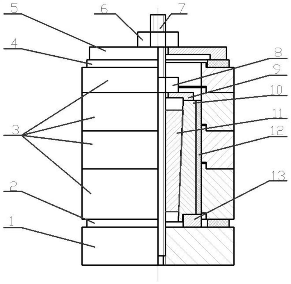
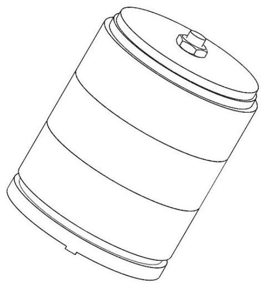
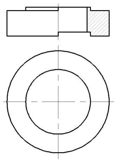

Image

  • Shock absorber capable of changing damping and adjusting mass and rigidity and rigidity quantitative regulation method
  • Shock absorber capable of changing damping and adjusting mass and rigidity and rigidity quantitative regulation method
  • Shock absorber capable of changing damping and adjusting mass and rigidity and rigidity quantitative regulation method

Examples


Embodiment Construction

[0026] The following will clearly and completely describe the technical solutions in the embodiments of the present invention with reference to the accompanying drawings in the embodiments of the present invention. Obviously, the described embodiments are only some, not all, embodiments of the present invention. Based on the embodiments of the present invention, all other embodiments obtained by those skilled in the art without making creative efforts belong to the protection scope of the present invention.

[0027] In order to make the above objects, features and advantages of the present invention more comprehensible, the present invention will be further described in detail below in conjunction with the accompanying drawings and specific embodiments.

[0028] The present invention provides a shock absorber with variable damping, adjustable mass and stiffness, such as Figure 1-Figure 6 As shown, it is characterized in that: the shock absorber includes a base 1, a lower rubb...


PUM


Abstract

The invention discloses a shock absorber capable of changing damping and adjusting mass and rigidity and a rigidity quantitative regulation method. The shock absorber comprises a base, two rubber washers, a mass block, a top end cover, a nut, a screw rod, an internal end cover, a lining, a regulating stopper, a rubber sleeve and a guide rail seat. When a system vibrates, the mass block vibrates under support of the rubber washers to absorb part of energy, and the interior of each of the rubber washers vibrates to consume part of energy, so that the purpose of realizing vibration attenuation ofa main system is realized. Mass regulation of the shock absorber is realized through the number of the mass block; vibration of the external diameter of the lining is controlled through the depth screwed into the regulating stopper to adjust damping of the shock absorber; the top end nut is screwed to adjust the compressing degree of the upper and lower rubber washers; quantitative regulation ofthe shock absorber rigidity is realized according to the relationship of the compression amount and the compressing rigidity of the rubber washers, and a better damping effect is realized without an experiment. The shock absorber is simple and compact in structure, can realize quantitative regulation of rigidity and mass and is wide in applicable range.

Description

technical field [0001] The invention relates to the technical field of vibration passive control, in particular to a shock absorber with variable damping, adjustable mass and stiffness and a quantitative adjustment method for stiffness. Background technique [0002] With the rapid development of modern industry and industry, high processing speed, high processing accuracy and high reliability have become the development trend in the field of mechanical processing. In this context, tiny vibrations in the machining process will affect the quality and efficiency of machining, and even cause damage to the entire machining system. Therefore, many scholars and engineers are devoted to the research and improvement of damping technology, and have designed many different forms of dampers. [0003] At present, there are mainly three modes of shock absorbers: passive control, active control and semi-active control. The dynamic vibration absorber based on passive control is the most w...

Claims


Application Information

Patent Timeline
IPC IPC(8): F16F7/108F16F15/08
CPCF16F7/108F16F15/08
Inventor 高相胜杨敬硕王民昝涛
Owner BEIJING UNIV OF TECH
Learn More