
Loading pressure-flow compensation balance valve

A technology of flow compensation and load pressure, which is applied in the direction of fluid pressure actuation device, fluid pressure actuation system components, servo motor components, etc. It can solve the problems of complex product structure, ineffective compensation effect of hydraulic power compensation balance valve, high cost, etc.

Active Publication Date: 2020-10-23
JIANGSU ADVANCED CONSTR MASCH INNOVATION CENT LTD +1
View PDF4 Cites 0 Cited by
  • Summary
  • Abstract
  • Description
  • Claims
  • Application Information

AI Technical Summary

Problems solved by technology

[0004] The compensation effect of the hydrodynamic compensation balance valve is not obvious, the flow rate decreases slightly with the increase of the load pressure, and the compensation effect is not adjustable; the balance valve adopts the servo control scheme, the compensation effect is controlled by damping, and the compensation effect is good and adjustable. Servo control is used, the product structure is complex, the parts are processed with high precision, and the cost is high

Method used


Image

  • Loading pressure-flow compensation balance valve
  • Loading pressure-flow compensation balance valve

Examples


Embodiment Construction

[0021] The present invention will be further described below in conjunction with the accompanying drawings. The following examples are only used to illustrate the technical solution of the present invention more clearly, but not to limit the protection scope of the present invention.

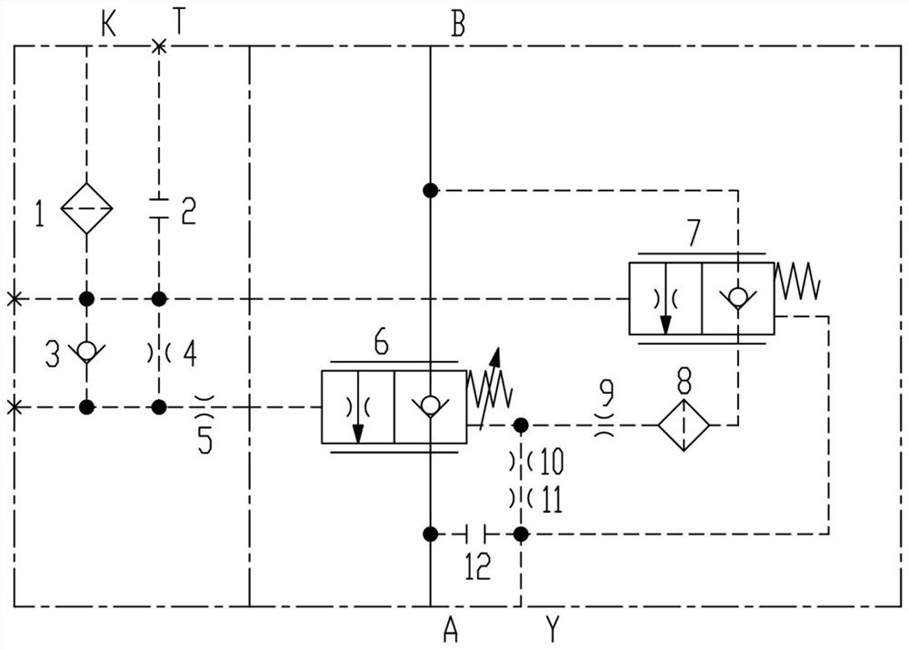
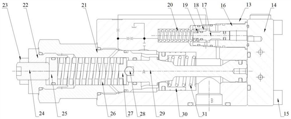
[0022] Such as figure 1 and figure 2 As shown, the present invention discloses a load pressure-flow compensation balance valve. The load pressure-flow compensation balance valve is composed of a control end cover 14 and a balance valve body assembly. The control end cover is composed of the first filter screen 1, the first screw plug 2, the one-way valve 3, the first damper 4 and the second damper 5; , the second filter screen 8, the third damper 9, the fourth damper 10, the fifth damper 11 and the second screw plug 12.

[0023] The control pressure from the luffing drop is connected to the K port of the control end cover 14, and the K port of the control end cover 14 passes through the first...


PUM


Abstract

The invention discloses a loading pressure-flow compensation balance valve. The loading pressure-flow compensation balance valve comprises a balance valve body, wherein a control end cover is installed on the balance valve body, an opening K of the control end cover is used for receiving control pressure from variable-amplitude falling, and is connected with a one-way valve, a first damper, one end of a first screwed plug and a two-position two-way reversing valve through a first filter screen, the one-way valve and the other end of the first damper are connected together and connected to a control cavity of a balance valve through a second damper, one end of the balance valve is connected with a variable-amplitude oil cylinder through a balance valve opening B, the other end of the balance valve is connected with a control valve through a balance valve opening A, spring cavities of the balance valve are connected with one end of a third damper and one end of a fourth damper correspondingly, the other end of the fourth damper and a fifth damper are connected in series and then are connected with one end of a second screwed plug, a spring cavity of the two-position two-way reversingvalve and a balance valve opening Y, and one oil end of the two-position two-way reversing valve is connected with the balance valve opening B. The loading pressure-flow compensation balance valve has the advantages of being simple in product structure, low in cost, good in compensation effect and capable of being adjusted conveniently.

Description

technical field [0001] The invention relates to a load pressure-flow compensating balance valve, which belongs to the technical field of engineering machinery with a luffing mechanism. Background technique [0002] Construction machinery such as truck cranes, crawler cranes, and rotary drilling rigs all have luffing mechanisms. When the luffing mechanism is falling, because the force arm of the luffing mechanism gradually increases, the falling speed of the luffing mechanism will become faster and faster. There may even be a stall, which can easily lead to safety accidents such as rollovers. If the load pressure-flow compensation balance valve is used in the luffing mechanism system, as the luffing mechanism falls, the load pressure will gradually increase, and the flow rate of the control balance valve will gradually decrease, so as to realize the stable falling of the luffing mechanism. [0003] At present, in order to realize the stable falling of the luffing mechanism, ...

Claims


Application Information

Patent Timeline
Patent Type & Authority Applications(China)
IPC IPC(8): F15B13/02F15B21/041B66C23/82
CPCF15B13/026B66C23/82F15B21/041
Inventor 孙辉刘莹莹肖刚
Owner JIANGSU ADVANCED CONSTR MASCH INNOVATION CENT LTD
Learn More