
Stirling engine structure

A Stirling engine and machine base technology, which is applied in the direction of machines/engines, hot gas variable displacement engine devices, mechanical equipment, etc., can solve problems such as complex installation and maintenance, engine volume, and large number of parts and components

Inactive Publication Date: 2020-10-23
杭州英洛威能源技术有限公司
View PDF6 Cites 0 Cited by
  • Summary
  • Abstract
  • Description
  • Claims
  • Application Information

AI Technical Summary

Problems solved by technology

[0003] The structure of the common Stirling engine is relatively complex and inconvenient to maintain. The cooler and regenerator in the Stirling engine are usually split and external, so that the number of parts and components is large, and the cost is high. The installation and maintenance are more complicated and the cost is higher, not only the engine volume and weight are larger, but also the heat loss is larger and the efficiency is lower; for example, the application number is CN2013106134289, and the application date is November 27, 2013. engine piston assembly, the patent's figure 1 The Stirling engine disclosed in [1] is to cool and exchange heat through an external cooler and regenerator. Its overall volume is relatively large, and various external pipelines are likely to cause heat loss, thereby reducing heat conversion efficiency.

Method used


Image

  • Stirling engine structure
  • Stirling engine structure
  • Stirling engine structure

Examples


Embodiment Construction

[0060] The present invention will be further described below in conjunction with accompanying drawing and specific embodiment:

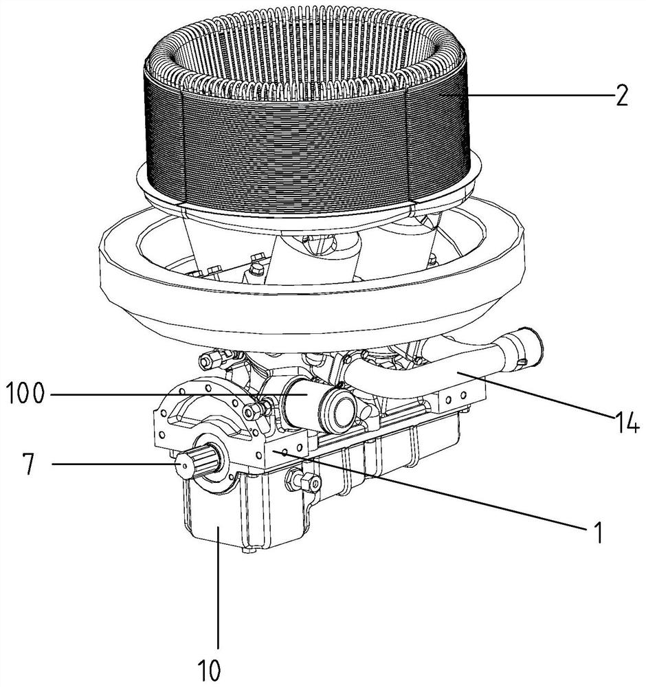
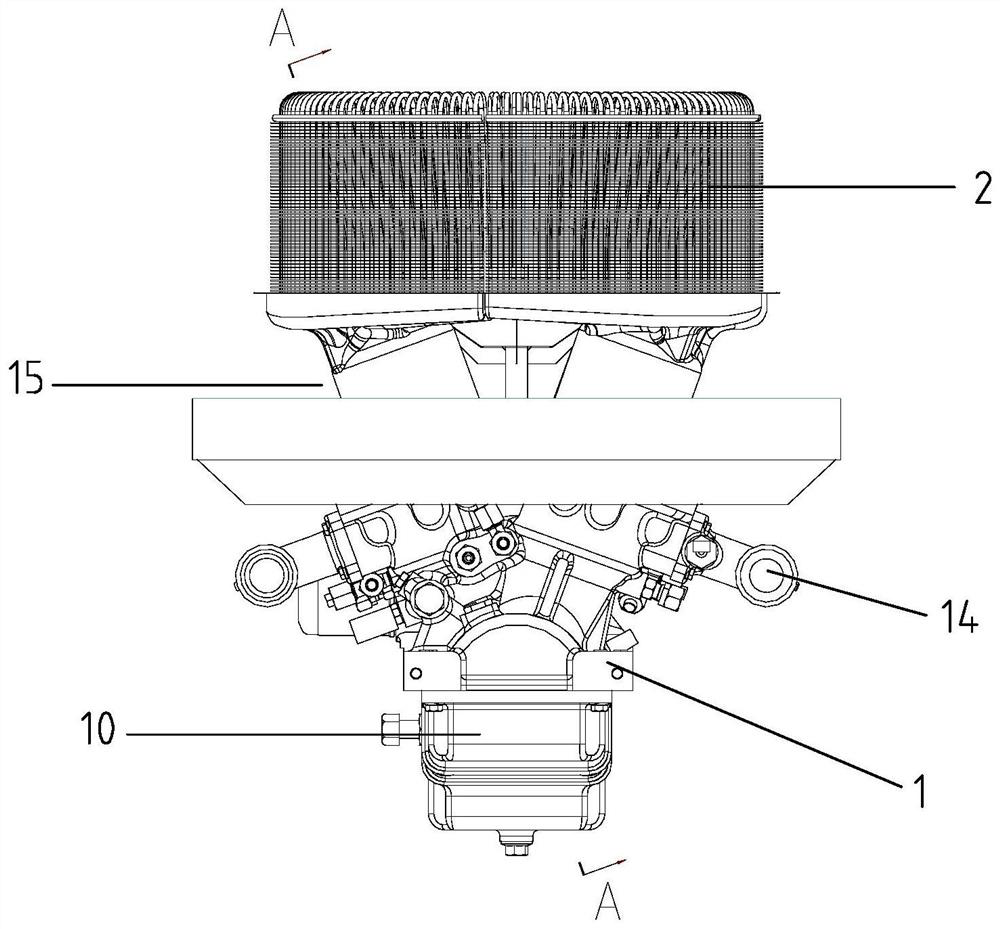
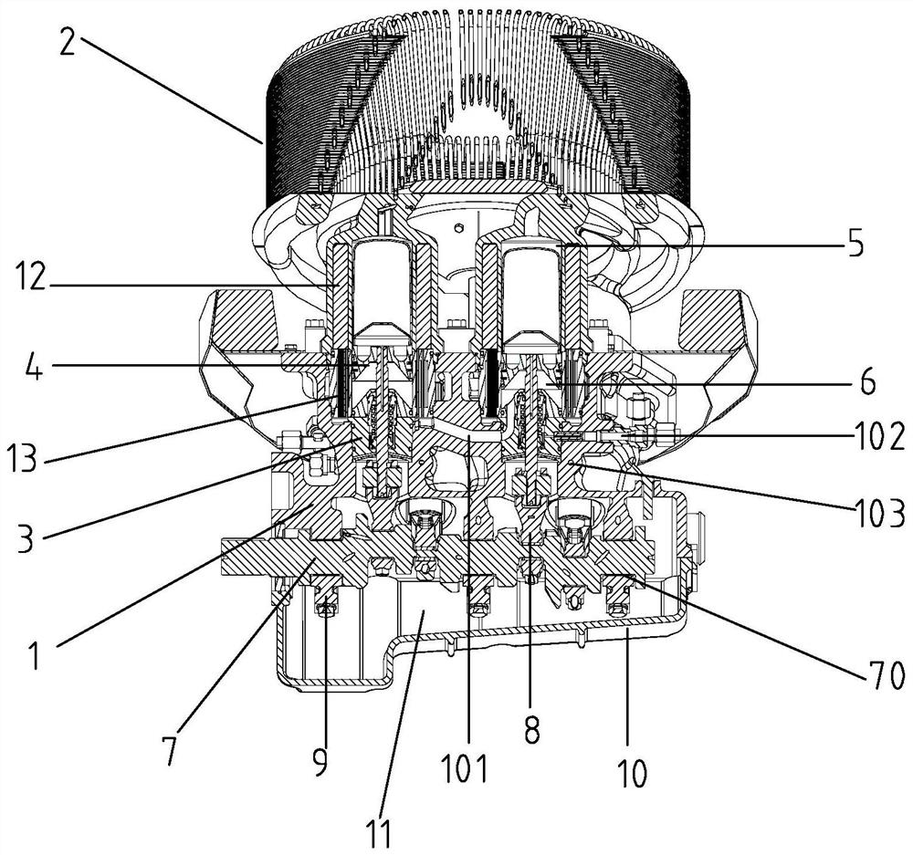
[0061] Such as Figure 1-Figure 8 The shown structure of a Stirling engine comprises a frame 1, the top surface of the frame 1 is provided with four cylinder holes 100, and the upper end of each cylinder hole 100 is provided with a heat collector assembly 2, and the heat collector assembly 2. It includes a cylinder liner 200 and a heat collector body 201. The open end of each cylinder liner 200 is in one-to-one sealing connection with the upper end of the cylinder hole 100. The bottom of each cylinder hole 100 is provided with a sealing assembly 3. The cylinder liner, cylinder The cavity in the hole forms a cylinder cavity, which is filled with a working medium, which is a gaseous working medium, and the gaseous working medium is hydrogen or helium; each cylinder cavity is equipped with a piston assembly 4, and the cylinder cavity is filled with a pi...


PUM

PropertyMeasurementUnit
Angleaaaaaaaaaa

Abstract

The invention relates to the technical field of engines, and discloses a Stirling engine structure. The Stirling engine structure comprises a machine base, four cylinder holes are formed in the top surface of the machine base, a heat collector assembly is arranged at the upper end of each cylinder hole, the heat collector assemblies comprise cylinder sleeves and heat collector bodies, an open endof each cylinder sleeve is hermetically connected to the upper end of each cylinder hole in a one-to-one correspondence mode, a sealing assembly is arranged at the bottom of each cylinder hole, cavities in the cylinder sleeves and the cylinder holes form cylinder cavities, the cylinder cavities are filled with working fluid, a piston assembly is arranged in each cylinder cavity, the cylinder cavities are divided into expansion cavities and compression cavities by the piston assemblies, and connecting rods and crankshafts connected with the piston assemblies are arranged on the lower side of the machine base; annular regenerative cavities are arranged in the cylinder sleeves, medium channels are arranged in the heat collector assemblies, regenerators are arranged in the annular regenerativecavities, coolers are arranged in the cylinder holes, the upper ends of the coolers are communicated with the annular regenerative cavities, and a diversion channel is arranged in the machine base. The Stirling engine structure has the beneficial effects of simple structure, low cost and high heat utilization rate.

Description

technical field [0001] The invention relates to the technical field of engines, in particular to a Stirling engine structure. Background technique [0002] The Stirling engine was invented by the British physicist Robert Stirling in 1816, hence the name "Stirling engine". The Stirling engine pushes the piston to do work through the pressure difference generated by the thermal expansion and exothermic contraction of the working medium (hydrogen, nitrogen or helium) in the cylinder, thereby converting heat energy into mechanical energy output, so it is also called a heat engine. The Stirling engine is an "external combustion" engine, and its working efficiency is generally between that of a gasoline engine and a diesel engine. The choice of fuel for the Stirling engine is relatively broad, basically including any heat source that can generate heat, whether it is liquid, gaseous or solid fuel, such as solar energy, biomass energy, various types of oil and gas, industrial waste...

Claims


Application Information

Patent Timeline
IPC IPC(8): F02G1/055F02G1/053F02G1/043
CPCF02G1/043F02G1/053F02G1/0535F02G1/055
Inventor 万斌郭向民
Owner 杭州英洛威能源技术有限公司
Learn More