
Material composite processing equipment

A composite processing and equipment technology, applied in the field of material composite processing equipment

Pending Publication Date: 2020-10-23
季亚珍
View PDF0 Cites 0 Cited by
  • Summary
  • Abstract
  • Description
  • Claims
  • Application Information

AI Technical Summary

Problems solved by technology

[0004] The purpose of the present invention is to provide a material composite processing equipment to solve technical problems such as improving the flatness of the back layer of material composite

Method used


Image

  • Material composite processing equipment
  • Material composite processing equipment

Examples


Embodiment 1

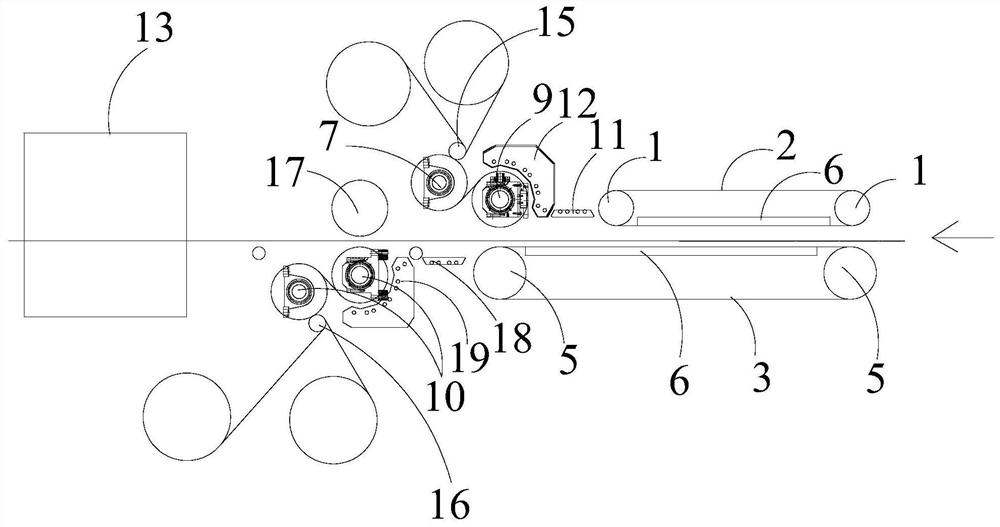
[0033] Such as figure 1 As shown, this embodiment provides a composite processing equipment for materials, including: a first-stage compound mechanism for compounding the first surface layer and the upper surface of the core layer arranged in sequence along the material conveying direction and for compounding the first surface layer The second-level composite mechanism for compounding the lower surface of the second surface layer and the core layer; that is to say, the second-level composite mechanism is located downstream of the first-level composite mechanism, and enters after the upper surface of the core layer completes the composite process with the first surface layer. The secondary composite mechanism performs the composite process of the lower surface of the core layer and the second surface layer.

[0034] In detail, the primary composite mechanism includes a core layer preheating assembly suitable for preheating the upper surface and the lower surface of the core lay...

Embodiment 2

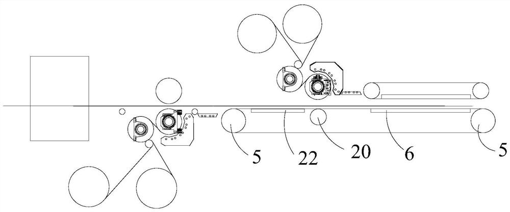
[0052] Such as figure 2As shown, the composite material processing equipment provided in this embodiment has the same general structure as the composite material processing equipment in Embodiment 1, the difference is that the composite material processing equipment in this embodiment also includes a pair of lower drive rollers 5 in the lower annular preheating structure A pressing roll 20 is added between them, and the pressing roll 20 is located directly below the No. 2 preheating roll 9 .

[0053] It should also be noted that the length of the lower annular preheating belt 3 of the present embodiment is that the lower annular preheating belt 3 of the present embodiment extends to the downstream of the first-level composite mechanism. For the composite between the upper surface and the first surface layer, the secondary composite mechanism starts to perform composite processing on the lower surface of the core layer and the second surface layer. Therefore, in order to effec...


PUM


Abstract

The invention discloses material composite processing equipment. The material composite processing equipment comprises a first-stage composite mechanism for compounding a first surface layer and the upper surface of a core layer and a second-stage composite mechanism for compounding a second surface layer and the lower surface of the core layer, which are sequentially arranged in the material conveying direction, wherein the first-stage compounding mechanism comprises a core layer preheating assembly suitable for preheating the upper surface and the lower surface of a core layer, a first preheating assembly suitable for preheating a first surface layer, and a first heating assembly suitable for heating the first surface layer and the upper surface of the core layer; and the second-stage compounding mechanism comprises a second preheating assembly suitable for preheating the second surface layer and a second heating assembly suitable for heating the second surface layer and the lower surface of the core layer. The material composite processing equipment can effectively improve the flatness of the material composite rear surface layer and improve the structural strength.

Description

technical field [0001] The invention relates to the technical field of material composite processing, in particular to a material composite processing equipment. Background technique [0002] Existing composite materials, the surface layer material and the core material are bonded with glue or hot melt. Due to the long curing time and poor process of glue bonding, the production efficiency is low and the environmental protection is affected. It is better to use hot-melt bonding. [0003] In the existing technology, when the surface layer material is hot-melt composited with core materials such as honeycomb core layer and foam core layer, it is mostly heated until the surface material melts, and then bonded to the core material, which causes the surface layer material to sag Into the pores of the core material, especially the honeycomb type core layer, resulting in uneven surface layer of the final product. Hot-melt film is also used for bonding, but it increases the produc...

Claims


Application Information

Patent Timeline
IPC IPC(8): B32B37/10B32B37/06B32B38/00
CPCB32B37/0053B32B37/06B32B37/10B32B38/004
Inventor 季亚珍其他发明人请求不公开姓名
Owner 季亚珍
Learn More