
Permanent magnet motor voltage adaptive control system and method

An adaptive control, permanent magnet motor technology, applied in the control system, AC motor control, power factor control and other directions, can solve problems such as aggravating the severity of the problem, the motor load rate cannot be improved, and restricting the development of the oilfield energy-saving industry.

Inactive Publication Date: 2020-10-20
日照正泽自动化科技有限公司
View PDF0 Cites 0 Cited by
  • Summary
  • Abstract
  • Description
  • Claims
  • Application Information

AI Technical Summary

Problems solved by technology

Compared with three-phase asynchronous motors, although the typical engineering test results of the vigorously promoted permanent magnet motors are very encouraging, large-scale tracking tests have found that more than half of the permanent magnet motors operate with a power factor below 0.5, and the energy consumption is similar to that of asynchronous motors. near
The power factor of the permanent magnet motor is close to 1, which is an important basis for replacing the asynchronous motor for energy-saving transformation. If the power factor of the permanent magnet motor is too low, it will lose its replacement value and advantages
In addition, a long-term follow-up test found that if the mechanical structure of the pumping unit cannot be changed, the load rate of the motor cannot be increased, and the permanent magnet motor will demagnetize after long-term use, which further aggravates the severity of the problem
More than half of permanent magnet motors in oilfields cannot achieve the desired energy-saving effect, and their performance is close to that of asynchronous motors, forming an embarrassing dilemma of "tasteless to eat, but a pity to discard", which seriously limits the development of energy-saving industries in oilfields. It also caused a huge consumption and waste of human, material and financial resources.

Method used


Image

  • Permanent magnet motor voltage adaptive control system and method
  • Permanent magnet motor voltage adaptive control system and method
  • Permanent magnet motor voltage adaptive control system and method

Examples


Embodiment Construction

[0082] Those of ordinary skill in the art can realize that the units and algorithm steps of the examples described in conjunction with the embodiments disclosed herein can be implemented by electronic hardware, computer software, or a combination of the two. In order to clearly illustrate the relationship between hardware and software Interchangeability. In the above description, the composition and steps of each example have been generally described according to their functions. Whether these functions are executed by hardware or software depends on the specific application and design constraints of the technical solution. Skilled artisans may use different methods to implement the described functions for each specific application, but such implementation should not be regarded as exceeding the scope of the present invention.

[0083] The block diagrams shown in the drawings are merely functional entities and do not necessarily correspond to physically separate entities. Tha...


PUM


Abstract

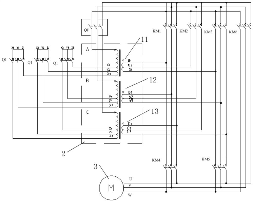
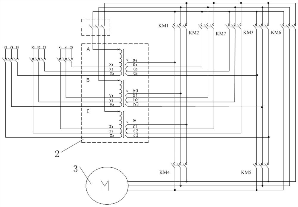
The invention provides a permanent magnet motor voltage adaptive control system and method. The system comprises a control device, three groups of three-phase power supplies, a three-phase transformerand a permanent magnet motor. A secondary coil of the three-phase transformer is connected with the permanent magnet motor through a relay and a control switch in the control device to control operation of the permanent magnet motor. The double-winding compensation transformer is adopted, forward and reverse series connection is carried out on windings to achieve multi-gear voltage, the remarkable advantages of being small in configuration capacity, small in operation loss, free of any harmonic wave and the like are achieved, and the control device achieves the operation mode of automatic detection and automatic control. The control device is used for calculating and processing various input data of the permanent magnet motor; and the current operation state of the permanent magnet motoris diagnosed according to the calculation result, the output voltage is automatically adjusted, automatic monitoring, automatic tracking and automatic regulation are sequentially realized, the optimaloperation voltage is provided for the permanent magnet motor, and the permanent magnet motor of the oil pumping unit is always in an efficient and economic operation state.

Description

technical field [0001] The invention relates to the technical field of permanent magnet motors, in particular to a permanent magnet motor voltage adaptive control system and method. Background technique [0002] The permanent magnet motor has the advantages of high efficiency and good power saving effect, and theoretically has a high power factor approximately equal to 1. At present, it has been rapidly popularized and applied on pumping units in oil fields. Compared with the three-phase asynchronous motors, although the typical engineering test results of the vigorously promoted permanent magnet motors are very encouraging, the large-scale tracking test found that more than half of the permanent magnet motors operate with a power factor below 0.5, and the energy consumption is similar to that of asynchronous motors. near. The power factor of the permanent magnet motor is close to 1, which is an important basis for replacing the asynchronous motor for energy-saving transfo...

Claims


Application Information

Patent Timeline
IPC IPC(8): H02P27/00H02P27/02H02P23/26
CPCH02P27/00H02P27/02H02P23/26
Inventor 徐衍亮王梓鉴于川皓于文涛闫敬东张文清于治华马文忠
Owner 日照正泽自动化科技有限公司
Learn More