
A cable tensioning device for high-altitude electric power construction

A tensioning device and high-altitude electric power technology, applied in the direction of overhead lines/cable equipment, etc., can solve problems such as high risk factor, difficulty in applying force, and single function, so as to avoid reverse rotation, protect construction safety, and reduce operating intensity. Effect

Inactive Publication Date: 2021-06-01
STATE GRID SHANDONG ELECTRIC POWER CO PINGYUAN POWER SUPPLY CO
View PDF10 Cites 2 Cited by
  • Summary
  • Abstract
  • Description
  • Claims
  • Application Information

AI Technical Summary

Problems solved by technology

[0002] When electricians carry out electric power construction, in order to ensure the safety and standardization of cable erection, they often need to tighten the cables. Cable tensioning operations are generally carried out at high altitudes, and are manually tightened by electricians, and electricians It is difficult to apply force when working at high altitudes, not only is it very laborious, but also the risk factor of tensioning operations at high altitudes is high, so it is necessary to use a cable tensioning device
[0003] However, the existing high-altitude cable tensioning device has a complex structure, which is not conducive to carrying it to high altitude for operation, or it has a single function, only has one function of tensioning, and it needs to carry many other tools to complete it when it is brought to high altitude. A complete set of procedures, for which we propose a cable tensioning device for high-altitude power construction

Method used


Image

  • A cable tensioning device for high-altitude electric power construction
  • A cable tensioning device for high-altitude electric power construction
  • A cable tensioning device for high-altitude electric power construction

Examples


Embodiment Construction

[0035] Attached below Figure 1-7 , clearly and completely describe the technical solutions in the embodiments of the present invention, obviously, the described embodiments are only some of the embodiments of the present invention, not all of them. Based on the embodiments of the present invention, all other embodiments obtained by persons of ordinary skill in the art without making creative efforts belong to the protection scope of the present invention.

[0036] In describing the present invention, it should be understood that the terms "longitudinal", "transverse", "upper", "lower", "front", "rear", "left", "right", "vertical", The orientations or positional relationships indicated by "horizontal", "top", "bottom", "inner", "outer", etc. are based on the orientations or positional relationships shown in the drawings, and are only for the convenience of describing the present invention, rather than indicating or It should not be construed as limiting the invention by imply...


PUM


Abstract

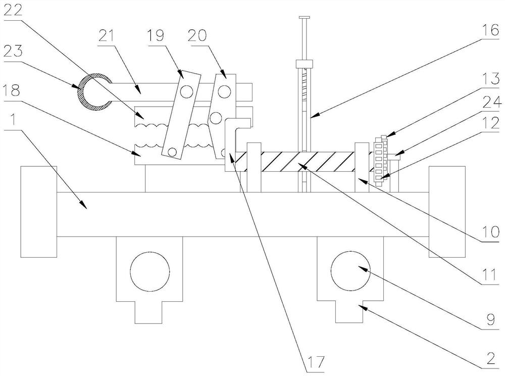
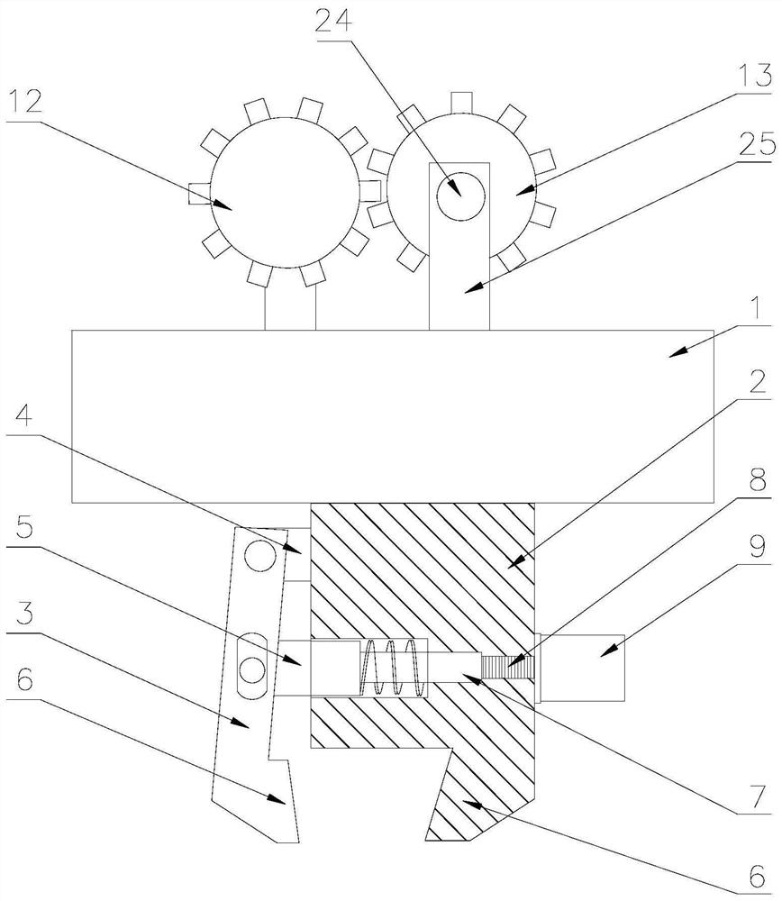
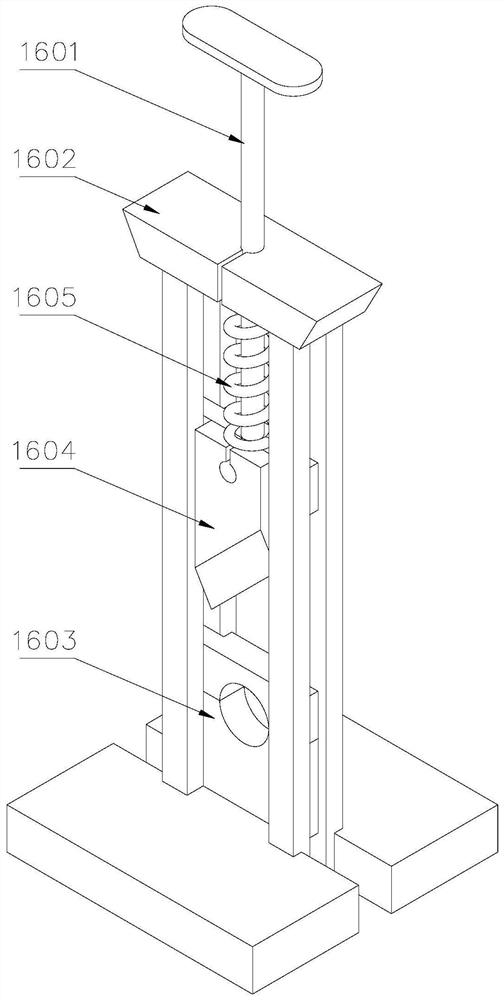
The invention discloses a cable tensioning device for high-altitude electric power construction, which comprises a base, a plurality of fixed main bodies arranged at the lower part of the base, a cable tightening rod arranged at the upper part of the base, and a movable clamp is hinged at one end of the fixing rod; the upper part of the base There are two sets of support frames, the two ends of the cable tightening rod are movably installed on the support frame through bearings, one end of the cable tightening rod is equipped with a rocker or a motor; one side of the cable tightening rod is fixedly installed on the The fixed splint on the upper part of the base, the upper part of the fixed splint is provided with a pull rod, one end of the pull rod is provided with a pull ring, the two sides of the pull rod and the fixed splint are provided with a first movable rod, one side of the first movable rod is provided with a second movable rod, and the lower part of the pull rod is provided with The movable splint is fixedly installed on one side of the first movable rod and the second movable rod. The present invention uses the fixed main body to fix the cable tensioning device on the electric pole or aerial ladder, starts the motor or rotates the rocker to tighten the cable, reduces the work intensity of the electrician, and protects the construction safety of the electrician.

Description

technical field [0001] The invention belongs to the technical field of cable construction, and particularly relates to a cable tensioning device for high-altitude electric power construction. Background technique [0002] When electricians carry out electrical construction, in order to ensure the safety and standardization of cable erection, it is often necessary to tighten cables. Cable tightening operations are generally carried out at high altitudes, and are manually tightened by electricians. It is difficult to apply force during high-altitude operations, which is not only very laborious, but also has a high risk factor for tensioning operations at high altitudes, so it is necessary to use a cable tensioning device. [0003] However, the existing high-altitude cable tensioning device has a complex structure, which is not conducive to carrying it to high-altitude operations, or it has a single function and only has one function of tensioning. A complete set of procedures...

Claims


Application Information

Patent Timeline
Patent Type & Authority Patents(China)
IPC IPC(8): H02G1/04
CPCH02G1/04
Inventor 王瑞贾翠庆周晓曼梁晓田忠禹张玉龙宋洪富祖林海王超路兴平
Owner STATE GRID SHANDONG ELECTRIC POWER CO PINGYUAN POWER SUPPLY CO
Learn More