Current collector for trolley conductor, construction hoist and power supply system

A technology for construction elevators and power supply systems, applied to collectors, non-rotating collectors, circuits, etc., can solve problems such as different running trajectories, increased project cost, and inability to exchange relative positional relationships

Active Publication Date: 2020-10-20
CHANGSHA HAICHUAN AUTOMATION EQUIP
View PDF4 Cites 2 Cited by
  • Summary
  • Abstract
  • Description
  • Claims
  • Application Information

AI Technical Summary

Problems solved by technology

[0003] Although the existing trolley line can support the power supply to multiple mobile devices on a single power transmission rail to simplify the field wiring of multiple mobile devices, the relative positional relationship between the various mobile devices often cannot be exchanged
However, in practical applications, due to the different mobile requirements between mobile devices, the running trajectories of each mobile device may be different; in addition, according to their respective mobile requirements, the length of pauses required by mobile devices may be different, which may also lead to different There is a need to change the relative position of space between mobile devices, which leads to the laying of power transmission guide rails, which increases the project cost and increases the cost

Method used


Image

  • Current collector for trolley conductor, construction hoist and power supply system
  • Current collector for trolley conductor, construction hoist and power supply system
  • Current collector for trolley conductor, construction hoist and power supply system

Examples


Embodiment Construction

[0050] In order to make the objectives, technical solutions, and advantages of the present invention clearer, the present invention will be further described in detail below with reference to the accompanying drawings. The described embodiments should not be regarded as limiting the present invention. Those of ordinary skill in the art have not made All other embodiments obtained under the premise of creative work belong to the protection scope of the present invention.

[0051] In the description of the present invention, “some embodiments” are involved, which describe a subset of all possible embodiments, but it is understood that “some embodiments” may be the same subset or different subsets of all possible embodiments, And can be combined with each other without conflict.

[0052] In the description of the present invention, the terms "first, second", etc. involved are only to distinguish similar objects, and do not represent a specific order for the objects. Understandably, "f...


PUM


Abstract

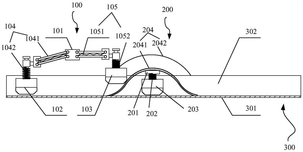
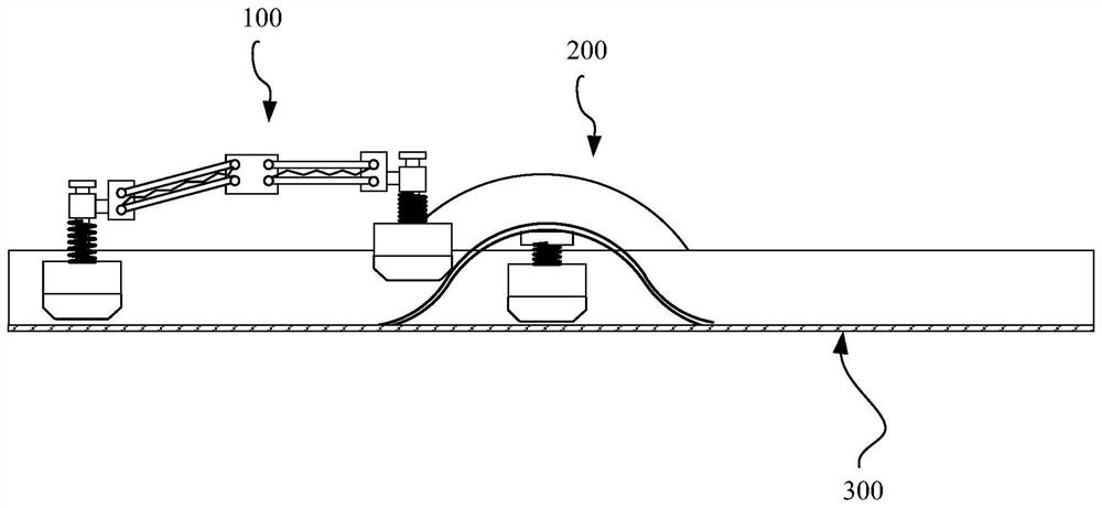
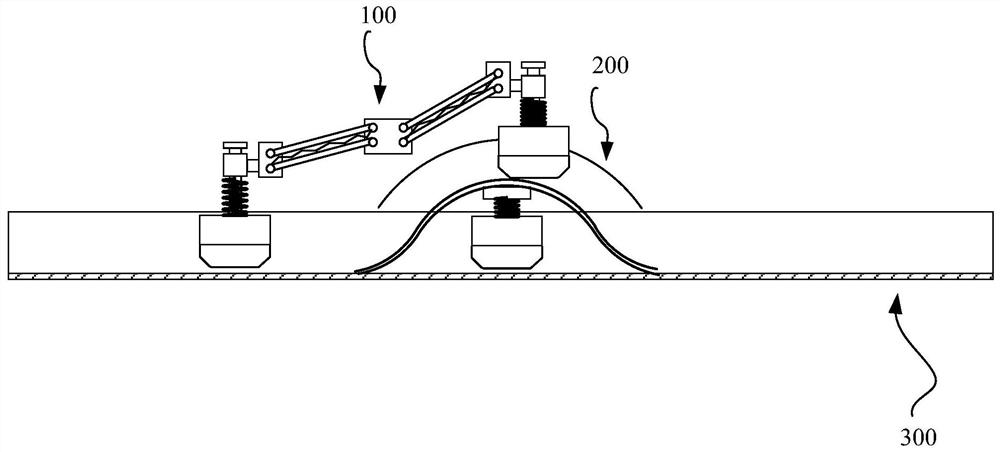
The invention discloses a current collector for a trolley conductor, a construction hoist and a power supply system. The current collector for the trolley conductor comprises a first current collectorand a second current collector, wherein the first current collector comprises a first mounting bracket used for being mounted on first mobile equipment, a first electric brush and a second electric brush which are used for being in contact with a conductive contact surface of a power transmission guide rail, a first pressing mechanism and a second pressing mechanism; the first mounting bracket isconnected with the first electric brush through the first pressing mechanism and is connected with the second electric brush through the second pressing mechanism; the second current collector comprises a second mounting bracket used for being mounted on second mobile equipment, a tensioning mechanism and a third electric brush used for being in contact with the conductive contact surface of thepower transmission guide rail, and the second mounting bracket is connected with the third electric brush through the tensioning mechanism; and a guide mechanism for guiding the first electric brush or the second electric brush to cross the second current collector is arranged on the second mounting bracket. According to the embodiment of the invention, two mobile devices can be supported to sharethe power transmission guide rail, and the spatial relative position between the two mobile devices can be exchanged.

Description

Technical field [0001] The invention relates to the field of power supply, in particular to a collector, a construction elevator and a power supply system for a sliding contact line. Background technique [0002] In the power supply field, equipment often uses cable power supply. But for mobile devices, since the mobile device needs to constantly change positions, in each different position, the mobile device must be able to get power at any time, otherwise it cannot continue to move. The use of cable for power supply has defects such as easy damage and difficult maintenance, and thus the isolated conductor rail (ICR) has emerged. The trolley line includes a power transmission rail laid in parallel along the running track of the mobile device and a current collector set on the mobile device for taking power from the power transmission rail. The current collector runs synchronously with the mobile device and obtains power from the power transmission rail at any time , Provided t...

Claims


Application Information

Patent Timeline
Patent Type & Authority Applications(China)
IPC IPC(8): H01R41/00
CPCH01R41/00
Inventor 倪建军
Owner CHANGSHA HAICHUAN AUTOMATION EQUIP
Why Eureka
Try Eureka