
Integrated ceramic ferrule and optical fiber socket

A ceramic ferrule, integrated technology, applied in the direction of light guide, optics, optical components, etc., can solve the problems of buffer protection channel metal part difference, high strength requirements of ceramic ferrule, high risk of problems, etc., to achieve temperature change stress reduction , Reliable product performance, Avoid possible effects of failure

Pending Publication Date: 2020-10-20
OECE COMM
View PDF0 Cites 2 Cited by
  • Summary
  • Abstract
  • Description
  • Claims
  • Application Information

AI Technical Summary

Problems solved by technology

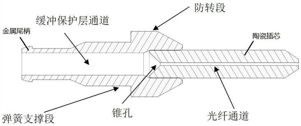
[0005] The existing ceramic ferrule components and ceramic sleeves are used as the core to design double-core, multi-core connectors and adapters. The above structure limits the distance between each ceramic ferrule, which needs to be greater than the anti-rotation section of the metal tail handle , plus the wall thickness of the material used to isolate each core, is the ceramic ferrule spacing of the existing dual-core connector, so the smallest SN connector spacing on the market is 3.1mm
[0006] If the structure of the buffer protection layer channel and the fiber channel remains unchanged, the inner diameter of the rear section of the outer edge of the ceramic ferrule is reduced, and then pressed into a tail handle with a smaller size than the tail handle used in the prior art In order to increase the density of optical fiber connectors, this structure has high requirements for the strength of the rear ceramic ferrule, and there is a step difference in the connection between the metal part and the ceramic part of the buffer protection channel, the production is difficult and the risk of problems is high

Method used


Image

  • Integrated ceramic ferrule and optical fiber socket
  • Integrated ceramic ferrule and optical fiber socket
  • Integrated ceramic ferrule and optical fiber socket

Examples


Embodiment Construction

[0031] In conjunction with the accompanying drawings and embodiments, the technical solution adopted in the present invention will be further described,

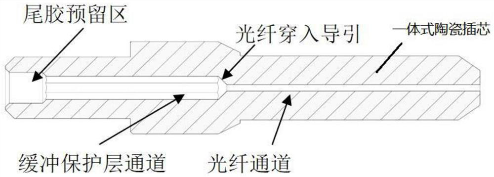
[0032] The present invention provides an integrated ceramic ferrule such as figure 2 As shown, the buffer protection layer channel originally in the metal tail handle is moved to the ceramic ferrule, and the anti-rotation and spring support structures are directly provided on the ceramic ferrule.

[0033] The front section of the inner hole of the integrated ceramic ferrule is a fiber channel for fixing the optical fiber, and there is a fiber penetration guide section at the end of the fiber channel.

[0034] The rear section of the inner hole of the integrated ceramic ferrule is a buffer layer protection channel for fixing the optical fiber buffer protection layer. And there is a tail glue area at the end to strengthen the protection of the optical fiber.

[0035] There is an anti-rotation structure on the outer edge str...


PUM


Abstract

The invention relates to the technical field of optical fiber communication, in particular to an integrated ceramic ferrule and an optical fiber socket. The integrated ceramic ferrule comprises an inner hole, the front section of the inner hole is an optical fiber channel for fixing an optical fiber, and the tail end of the optical fiber channel is provided with an optical fiber penetration guidesection. The rear section of the inner hole is a buffer layer protection channel used for fixing an optical fiber buffer protection layer, an anti-rotation structure is arranged on the outer edge structure of the rear section of the ceramic ferrule, and a spring supporting section is arranged on the rear portion of the anti-rotation structure. According to the integrated ceramic ferrule and the optical fiber socket provided by the invention, through combination of a ceramic ferrule part and a metal tail handle part and because of reasonable structural design of an optical fiber connector, theoptical fiber connector is more compact in structure, therefore, the density of the current optical fiber connector is doubled, and preparation is made for an optical module to achieve a specificationof 800G and above in the next step.

Description

technical field [0001] The invention relates to the technical field of optical fiber communication, in particular to an integrated ceramic ferrule and optical fiber socket. Background technique [0002] With the continuous increase in data bandwidth requirements and the continuous evolution of data centers to 400G / 800G, higher and higher requirements are placed on the miniaturization of optical module sizes. Optical fiber connectors, as connection products that cooperate with optical modules, have higher and higher density requirements. The traditional LC connectors have been gradually eliminated and replaced by smaller fiber optic connectors such as CS, SN, and MDC. [0003] The size of the multi-core optical fiber connector with the ceramic ferrule as the core depends on the optimal design of the external structure and the rational use of space, the most critical factor is the spacing between the ceramic ferrules. With the evolution of optical fiber connectors to miniatu...

Claims


Application Information

Patent Timeline
Patent Type & Authority Applications(China)
IPC IPC(8): G02B6/38
CPCG02B6/3825G02B6/3887G02B6/3897
Inventor 金建峰余艳梅
Owner OECE COMM
Learn More