
A power module testing tool and testing method

A technology of power module and test method, applied in power test and other directions, can solve the problems of low batch test efficiency, test failure, poor contact of components, etc., and achieve the effect of high batch test efficiency, high reliability and easy disassembly

Active Publication Date: 2021-12-10
SHANGHAI JARI INFORAMTION SCI & TECH
View PDF8 Cites 0 Cited by
  • Summary
  • Abstract
  • Description
  • Claims
  • Application Information

AI Technical Summary

Problems solved by technology

[0003] Traditional power module test fixtures have a variety of structures, but the general structure is complex, the tolerance rate of assembly is low, and because there are too many active components, under a large number of human operations, it often leads to poor contact or even test failure due to component aging and wear or misoperation. In addition, due to the many actual operation steps, the efficiency of batch testing is low, which seriously restricts the engineering production and test management of power module products

Method used


Image

  • A power module testing tool and testing method
  • A power module testing tool and testing method
  • A power module testing tool and testing method

Examples


Embodiment Construction

[0027] In order to make the purpose, technical solutions and advantages of the embodiments of the present invention clearer, the following will clearly and completely describe the technical solutions in the embodiments of the present invention in conjunction with the accompanying drawings of the present invention. Obviously, the described embodiments are part of the present invention Examples, not all examples. Based on the embodiments of the present invention, all other embodiments obtained by persons of ordinary skill in the art without making creative efforts belong to the protection scope of the present invention.

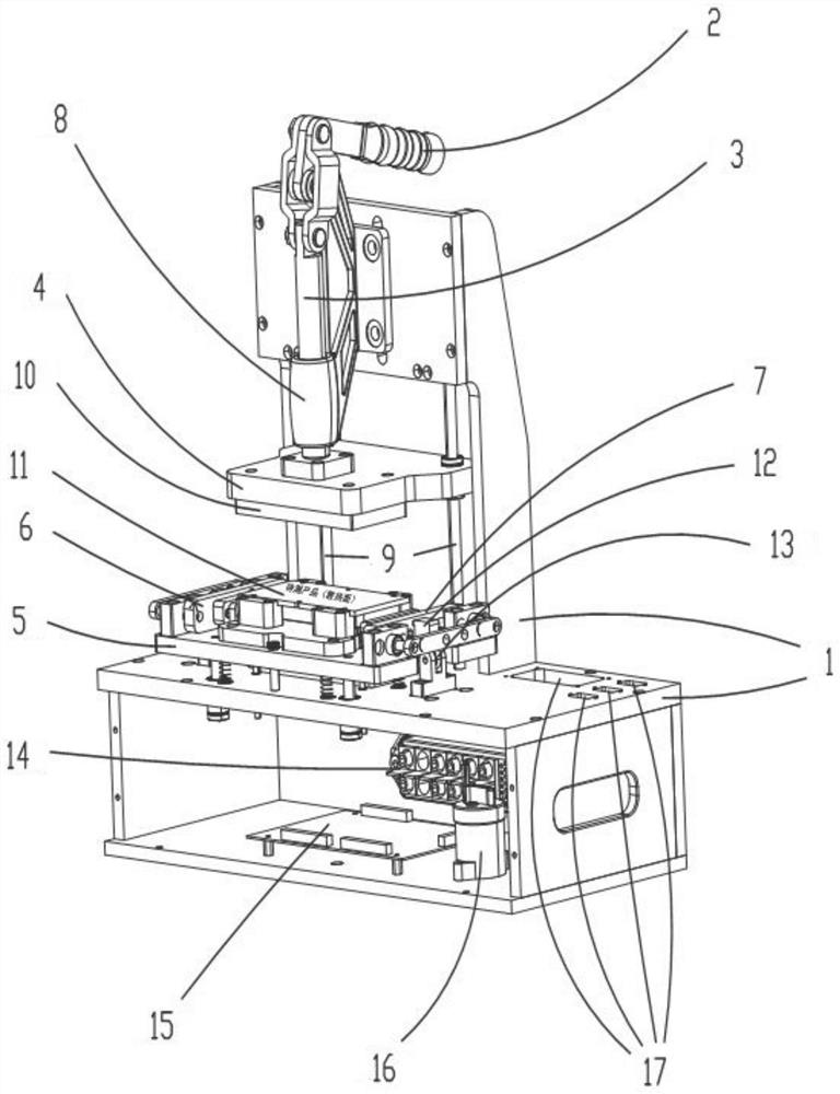
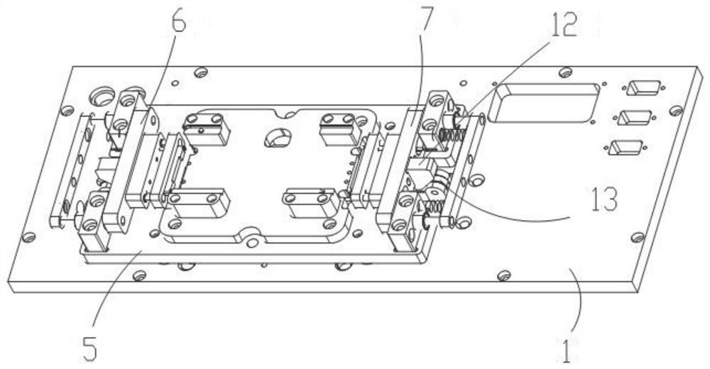
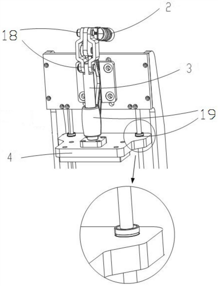
[0028] refer to Figure 1-5 , a power module test tool, including a frame 1, a handle 2, a lifting shaft 3, a horizontal platen member 4, an insulating mounting seat 5, a first test member 6, a second test member 7, and the handle 2 is the only part of the test tool The active part and other components are driven parts, and the linkage of all components can be...


PUM


Abstract

A power module testing tooling, the tooling includes a frame, an insulating mounting seat is installed on the frame, and a positioning groove for placing the power module is arranged on the insulating mounting seat, and two sides of the insulating mounting seat are respectively installed for testing the product to be tested. For the first test component and the second test component to be tested, a horizontal pressing plate component cooperating with the insulating mounting base for testing the power module is also movably installed on the frame above the positioning groove. The tolerance of each component is fully considered in the design of the tooling, and the linkage is realized in the simplest and least stressful way, and the insulating mounting seat of the key component carrying the power module is easy to disassemble and maintain; so the overall use of the test tooling, batch testing Higher efficiency and higher reliability.

Description

technical field [0001] The present invention relates to the technical field of power module testing, in particular to a power module testing tool, and also relates to a testing method for the power module testing tool. Background technique [0002] With the development of power supply technology, high power density power supply modules are widely used due to their high reliability, convenient use, and short development cycle. Their main features are high power density, rich functions, and mature technology, and they occupy a large market in the field of military power supplies. market. [0003] Traditional power module test fixtures have a variety of structures, but the general structure is complex, the tolerance rate of assembly is low, and because there are too many active components, under a large number of human operations, it often leads to poor contact or even test failure due to component aging and wear or misoperation. In addition, due to the many actual operation s...

Claims


Application Information

Patent Timeline
Patent Type & Authority Patents(China)
IPC IPC(8): G01R31/40
CPCG01R31/40
Inventor 吴超郝英杰杨涛孙娟师贺顾亮严凯邰阳徐一民冉云飞
Owner SHANGHAI JARI INFORAMTION SCI & TECH
Learn More