Eureka AIR delivers breakthrough ideas for toughest innovation challenges, trusted by R&D personnel around the world.

Plasma intensified chemical vapour deposition device

A plasma, enhanced chemical technology, applied in gaseous chemical plating, semiconductor/solid-state device manufacturing, coating, etc., can solve problems such as reduced barrier properties, poor thin metal uniformity, etc., to enhance device performance and improve production. The effect of yield

Inactive Publication Date: 2003-08-13
NEC CORP
View PDF2 Cites 2 Cited by
  • Summary
  • Abstract
  • Description
  • Claims
  • Application Information

AI Technical Summary

Problems solved by technology

That is, different parts of the base have different temperatures, resulting in poor uniformity of the thin metal, resulting in different electrical properties of the film
Moreover, the titanium nitride thin film formed by the above-mentioned chemical vapor deposition apparatus has many crystal grains, resulting in lowered barrier characteristics.

Method used


Image

  • Plasma intensified chemical vapour deposition device
  • Plasma intensified chemical vapour deposition device
  • Plasma intensified chemical vapour deposition device

Examples


Embodiment 2

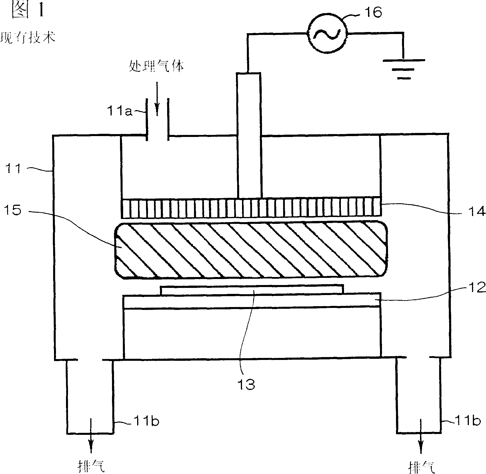
[0048] Figure 4 A plasma chemical vapor deposition apparatus according to a second embodiment of the present invention is shown.

[0049] The plasma enhanced chemical vapor deposition apparatus of the second embodiment of the present invention differs from the first embodiment only in that it includes an inner bell jar 38 instead of the susceptor lid 28 . The inner bell 38 has a susceptor covering portion 38a covering the second region 32b of the susceptor 32, and an insulating portion 38b extending between the inner wall 31a of the reaction chamber 31 and the plasma 25 to isolate them. That is, the inner bell 38 is placed on the base 32 upside down. In this way, the bottom end of the inner bell jar 38 faces the electrode 34 and the top end rests on the base 32 .

[0050] The inner bell 38 is formed with an opening 38c in the base cover portion 38a which is coextensive with the first region 32a of the base 32 in which the silicon substrate 33 is disposed.

[0051] The part...


PUM

PropertyMeasurementUnit
thicknessaaaaaaaaaa
thicknessaaaaaaaaaa

Abstract

There is provided a plasma-enhanced chemical vapor deposition apparatus including a reaction chamber into which a process gas is introduced and from which an exhausted gas is discharged, a susceptor having a first region on which a semiconductor substrate is to be placed and a second region other than the first region, and an electrode located in facing relation with the susceptor and cooperating with the susceptor to generate plasma therebetween for forming a thin film on the semiconductor substrate placed on the first region of the susceptor, characterized by a ceramics insulator located between the second region of the susceptor and the plasma.

Description

technical field [0001] The invention relates to a plasma-enhanced chemical vapor deposition device for forming thin films in the process of preparing semiconductor devices, in particular to a plasma-enhanced chemical vapor deposition device capable of uniformly forming metal films with high barrier properties. Background technique [0002] Recently, with the miniaturization and high integration of LSI fabrication, the design rules of semiconductor devices have been raised from half a micron to a quarter micron level. In addition, techniques for forming multilayer wiring structures and planarizing device surfaces use increasingly larger aspect ratios of contact holes connecting upper and lower wiring layers. In order to form a highly reliable multilayer wiring structure including these high-aspect-ratio contact holes, various methods have been employed. For example, one of the methods includes the steps of: forming a titanium nitride layer functioning as a barrier metal, whi...

Claims


Application Information

Patent Timeline
Patent Type & Authority Patents(China)
IPC IPC(8): C23C16/06C23C16/08C23C16/34C23C16/50C23C16/509H01J37/32H01L21/205H01L21/285
CPCH01J37/32495H01J37/32642H01L21/205
Inventor 田桑哲也
Owner NEC CORP
Why Eureka
Eureka Blog
Learn More