
Fluid pump for ship and method for controlling same

A control method and fluid pump technology, applied in electrical control, engine control, fuel injection control, etc., can solve problems such as high cost, unsuitable solenoid valve, and foreign matter mixing, and achieve the effect of suppressing cost increase

Active Publication Date: 2020-10-16
JAPAN ENGINE CORP
View PDF8 Cites 0 Cited by
  • Summary
  • Abstract
  • Description
  • Claims
  • Application Information

AI Technical Summary

Problems solved by technology

However, when using an opening adjustment type solenoid valve as a control valve, in general, it is necessary to frequently measure the actual value of the movement amount of the piston during the ejection of the fluid, and it is necessary to adjust the movement amount of the piston every time. The deviation between the actual measured value and the target value is reflected in the adjustment of the opening degree of the control valve, so there is a concern that the structure of the device for controlling the movement amount of the piston with high precision will become complicated and the cost of the device will increase.
In addition, most opening-adjustable solenoid valves are not good at dealing with the incorporation of foreign matter, and it is easy to cause foreign matter to enter in an environment where a marine diesel engine is operating. Therefore, as a control valve for a marine fluid pump, an opening-adjustable solenoid valve may not Be applicable

Method used


Image

  • Fluid pump for ship and method for controlling same
  • Fluid pump for ship and method for controlling same
  • Fluid pump for ship and method for controlling same

Examples


Embodiment Construction

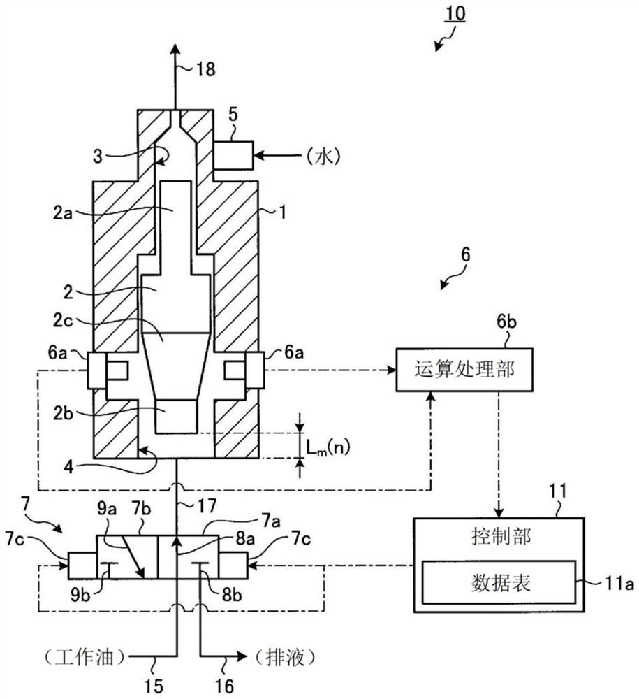
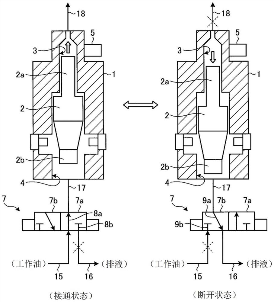
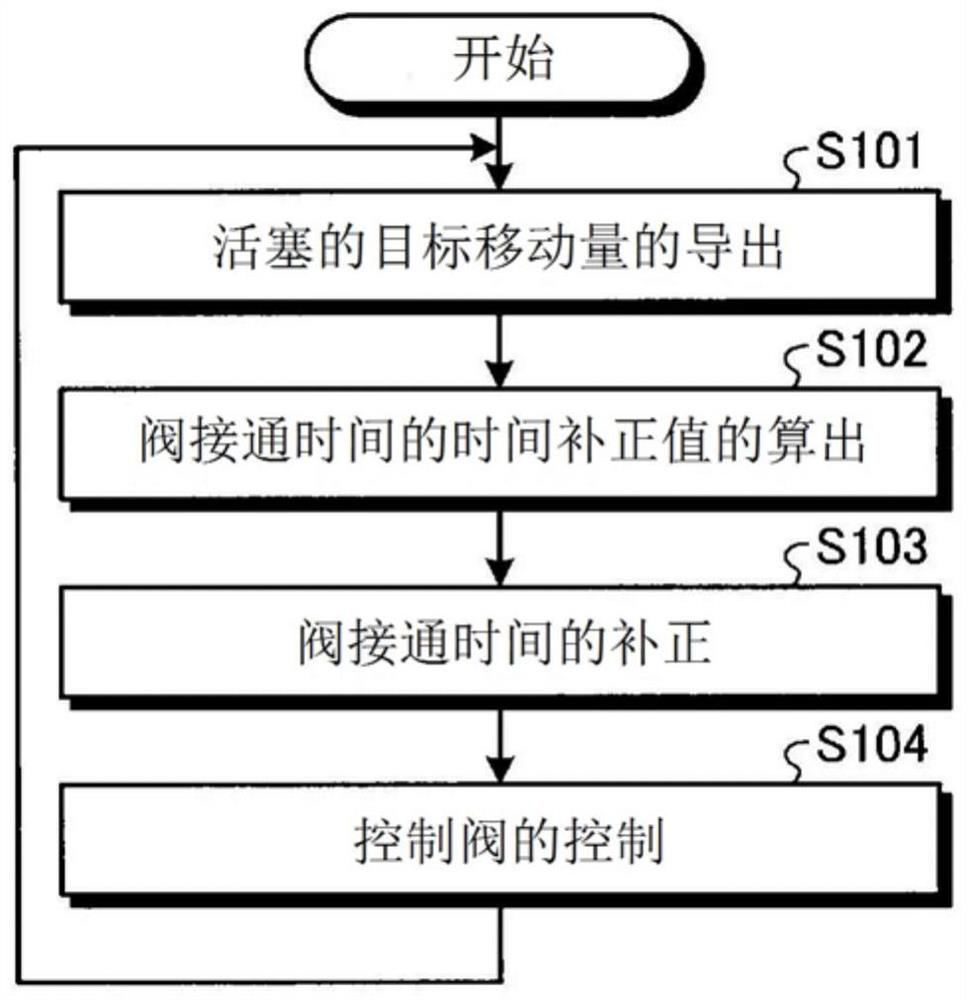
[0023] Hereinafter, preferred embodiments of the marine fluid pump and its control method according to the present invention will be described in detail with reference to the drawings. In addition, this invention is not limited by this embodiment. In addition, the drawings are schematic diagrams, and it is necessary to pay attention to the fact that the dimensional relationship of each element, the ratio of each element, and the like may be different from reality. Between the drawings, there may be a portion where the relationship and ratio of mutual dimensions are different. In addition, in each figure, the same code|symbol is attached|subjected to the same component.

[0024] (Structure of marine fluid pump)

[0025] figure 1 It is a schematic diagram showing a configuration example of the marine fluid pump according to the embodiment of the present invention. In the present embodiment, a case where the marine fluid pump 10 is an injection pump for injecting water into a...


PUM


Abstract

A fluid pump for a ship, which is one aspect of the present invention, comprises a pump body that pressurizes and discharges a fluid by moving a piston in which pressure of hydraulic oil is used, a detection unit that detects a maximum movement amount of the piston in one fluid discharge, a control valve that selectively switches between an ON state in which hydraulic oil is supplied to the pump body and an OFF state in which the supply of hydraulic oil is stopped, and a control unit. The control unit derives a target movement amount of the piston in accordance with a fluid discharge amount required in one fluid discharge. On the basis of the difference between the target movement amount in the current fluid discharge and the maximum movement amount in the previous fluid discharge, the control unit calculates a time correction value for a valve ON time of the control valve, adds this time correction value to correct the valve ON time during the current fluid discharge, and controls thecontrol valve so that the valve continues to be in an ON state for the corrected valve ON time.

Description

technical field [0001] The invention relates to a marine fluid pump and a control method thereof. Background technique [0002] Conventionally, marine fluid pumps for discharging fluids such as fuel and water have been used in marine diesel engines mounted on ships. For example, examples of marine fluid pumps include a fuel injection pump that pressurizes fuel injected into a cylinder to a fuel injection valve, and a fuel injection pump that injects fuel into a fuel flow passage that reaches the injection port of the fuel injection valve through piping from the discharge port of the fuel injection pump. Water injection pump, etc. Patent Document 1 describes a fuel injection pump driven and controlled by hydraulic oil supplied via a solenoid valve. [0003] In general, a marine fluid pump has a piston reciprocally movable in its longitudinal direction inside, and the piston is moved by the pressure of working oil supplied through a control valve to pressurize and discharge ...

Claims


Application Information

Patent Timeline
Patent Type & Authority Applications(China)
IPC IPC(8): F02M47/00F02D19/12F02D41/38F02D41/40F04B9/103
CPCF02D41/40F04B9/103F02D19/12F02M47/00F02D41/38F02M47/025B63H21/14
Inventor 柿元泰和泉基辉
Owner JAPAN ENGINE CORP
Learn More