Optical cable distribution box

A distribution box and optical cable technology, applied in the field of optical cable distribution box, can solve the problem that the optical cable distribution box cannot take into account the quality of compact optical channel connection, achieve compact optical channel connection quality, reduce maintenance costs, and high quality optical channel connection Effect

Active Publication Date: 2020-10-16
LUOHE POWER SUPPLY OF HENAN ELECTRIC POWER CORP
View PDF10 Cites 0 Cited by
  • Summary
  • Abstract
  • Description
  • Claims
  • Application Information

AI Technical Summary

Problems solved by technology

[0004] The purpose of this invention is to provide an optical cable distribution box to solve the technical problem that the existing optical cable distribution box cannot take into account the compactness and the connection quality of the optical channel

Method used


Image

  • Optical cable distribution box
  • Optical cable distribution box
  • Optical cable distribution box

Examples


Embodiment 1

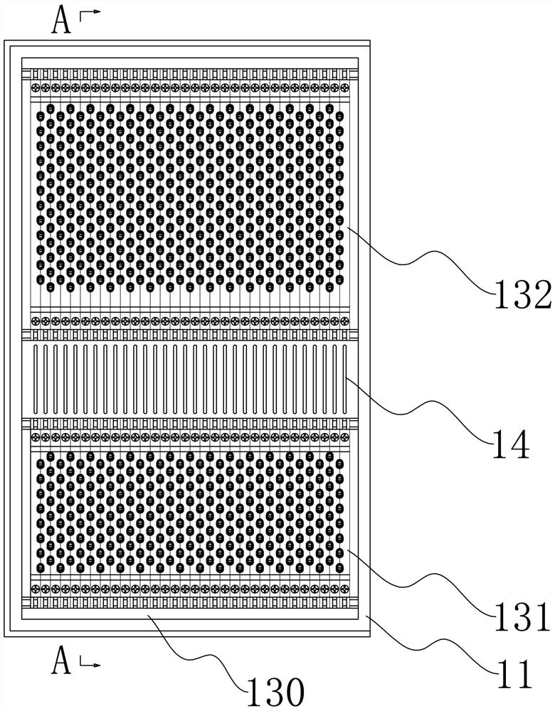
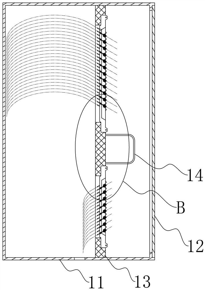
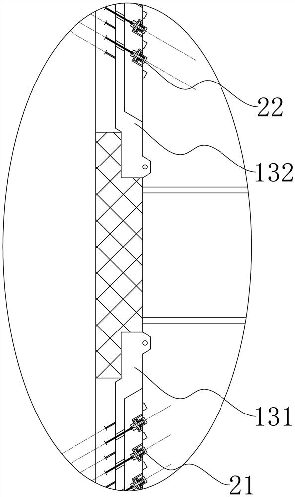
[0024] Embodiment 1: A kind of optical cable distribution box, see Figure 1-3 , including a cabinet body, an incoming optical fiber connector 22 and an outgoing optical fiber connector 21.

[0025] Generally, the cabinet mainly includes a cabinet body and a cabinet door. Cabinet doors can have one, two, or more.

[0026] An obtuse angle is formed between the end extension line of the incoming optical fiber connector 22 and the end extension line of the outgoing optical fiber connector 21 . In the optical cable distribution box, the end extension line of the optical fiber connector refers to the axis ray of the optical fiber connector extending from the end of the optical fiber connector to the side without the pigtail. see figure 2 , the end extension line of the fiber optic connector extends to the right side of the cabinet.

[0027] When in use, the incoming optical fiber connector 22 is connected to the lead-in optical cable, the outgoing optical fiber connector 21 is...


PUM


Abstract

The invention provides an optical cable distribution box, and belongs to the field of optical fiber connection. The optical fiber distribution box comprises a cabinet body, an incoming optical fiber connector and an outgoing optical fiber connector, wherein an obtuse included angle is formed between an end extension line of the incoming optical fiber connector and an end extension line of the outgoing optical fiber connector. Compact and optical channel connection quality can be considered.

Description

technical field [0001] The invention relates to the technical field of optical fiber connection, in particular to an optical cable distribution box. Background technique [0002] The optical transmission and communication bearing medium of the substation is an optical cable, and the optical cable in the lead field and the optical cable in the main control room are usually connected by jumpers at the optical cable distribution box, which is convenient for the connection and maintenance of optical fibers. [0003] Patent document CN204302551U describes a new type of non-jump fiber optic cable transfer box, which includes a cabinet body and a base. The cabinet is provided with a trunk fiber unit panel and a distribution fiber unit panel. The trunk fiber unit panel is set in the cabinet On one side of the body, the distribution fiber unit panel is set on the other side of the cabinet opposite to the main fiber unit panel, and the pigtails in the distribution fiber unit panel ext...

Claims


Application Information

Patent Timeline
Patent Type & Authority Applications(China)
IPC IPC(8): G02B6/44
CPCG02B6/4471
Inventor 李亮付永健曹俊超王永翔李臻郭薇耿飞刘海燕赵永刚
Owner LUOHE POWER SUPPLY OF HENAN ELECTRIC POWER CORP
Why Eureka
Try Eureka