a stepped energy dissipator

An energy dissipator and ladder technology, applied in marine engineering, water conservancy engineering, construction, etc., can solve the problems of single-width flow restriction and high requirements for initial aeration position, reduce kinetic energy, change the size of eddy current, and eliminate water flow energy. Effect

Active Publication Date: 2021-07-30
河北科乾信息技术服务有限公司
View PDF6 Cites 0 Cited by
  • Summary
  • Abstract
  • Description
  • Claims
  • Application Information

AI Technical Summary

Problems solved by technology

At present, the use of conventional stepped energy dissipators has two major limitations. One is the high requirement for the initial aeration position, and the other is the restriction on the single-width flow rate of the discharge.

Method used


Image

  • a stepped energy dissipator
  • a stepped energy dissipator
  • a stepped energy dissipator

Examples


Embodiment Construction

[0016] The standard parts used in the present invention can be purchased from the market, and the special-shaped parts can be customized according to the instructions and the accompanying drawings. The specific connection methods of each part adopt mature bolts, rivets, welding in the prior art , pasting and other conventional means, no longer described in detail here.

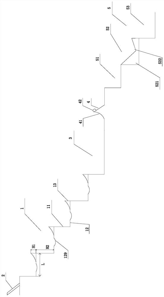
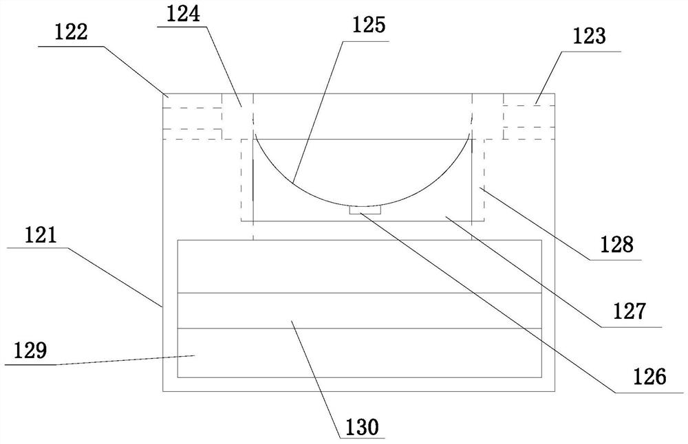
[0017] refer to Figure 1-5 A specific embodiment of the present invention sequentially includes a first multi-level ladder 1, a stilling pool 3, a triangular prism stilling sill 4 and a second multi-level ladder 5 along the water flow direction, and the water flow upstream of the first multi-level ladder 1 is fixed There is an aeration device 2, and the first multi-level ladder 1 includes several end-to-end connecting horizontal ladders 12 and vertical ladders 11, the horizontal ladders 12 are movably connected with a stagnation block 13, and the horizontal ladders 12 are provided with a first arc-shaped groo...


PUM


Abstract

The invention discloses a ladder energy dissipator, which sequentially comprises a first multi-level ladder, a stilling pool, a triangular prism stilling sill and a second multi-level ladder along the direction of water flow. In the device, the first multi-level ladder includes several horizontal ladders and vertical ladders connected end to end, the horizontal ladders are movably connected with stagnation blocks, the horizontal ladders are provided with first arc-shaped grooves, and the stagnation blocks are located downstream of the first arc-shaped groove water flow, The second multi-stage ladder includes a first ladder, a second ladder and a third ladder connected end to end along the water flow direction, the second ladder is fixed with a trapezoidal prism water blocking block, and the side of the trapezoidal prism water blocking block is provided with a triangular prism groove , the horizontal ladder includes a horizontal ladder body, and the downstream of the horizontal ladder body is symmetrically provided with two cuboid inner grooves, one end of the hydraulic device is connected to the side of the cuboid inner groove, and the other end of the hydraulic device is connected to the side of the cuboid block. The deficiencies of the prior art can be solved, and the energy dissipation effect of the stepped energy dissipation work is enriched.

Description

technical field [0001] The invention relates to the field of water conservancy engineering of a flood discharge efficiency facility, in particular to a ladder efficiency facility. Background technique [0002] Most of the high dam projects in my country are located in the mountains and canyons in the west. In terms of flood discharge efficiency, they have the characteristics of high water head, large flow, large flood discharge power, and narrow river valleys. The stepped efficiency tool can use the overflow dam or the steep trough section to eliminate most of the kinetic energy of the water flow, and is widely used in energy discharge and flood reduction. With the continuous development of my country's hydropower industry, the stepped efficiency tool has huge economic benefits and promotion value. At present, the use of conventional stepped energy dissipators has two major limitations. One is the high requirement for the initial aeration position, and the other is the restr...

Claims


Application Information

Patent Timeline
Patent Type & Authority Patents(China)
IPC IPC(8): E02B8/06E02B8/00
CPCE02B8/00E02B8/06
Inventor 李书芳路明赵营张伟王方勇高子兰
Owner 河北科乾信息技术服务有限公司
Why Eureka
Try Eureka