Automatic splicing device for broken yarns

A wire connector and automatic technology, which is applied in jointing devices, textiles, papermaking, spinning machines, etc., can solve problems such as inconvenient handling and carrying, complex structure of wiring devices, and broken spinning threads, etc., to achieve convenient wiring and operation Simple, convenient and portable effect

Active Publication Date: 2020-10-16
吴江兴宇经编有限公司
View PDF5 Cites 0 Cited by
  • Summary
  • Abstract
  • Description
  • Claims
  • Application Information

AI Technical Summary

Problems solved by technology

[0002] During the spinning process, the spinning yarn is prone to breakage, and wiring operations are required. The traditional wiring device has a complicated structure and is inconvenient to hold and carry.

Method used


Image

  • Automatic splicing device for broken yarns
  • Automatic splicing device for broken yarns
  • Automatic splicing device for broken yarns

Examples


Embodiment 1

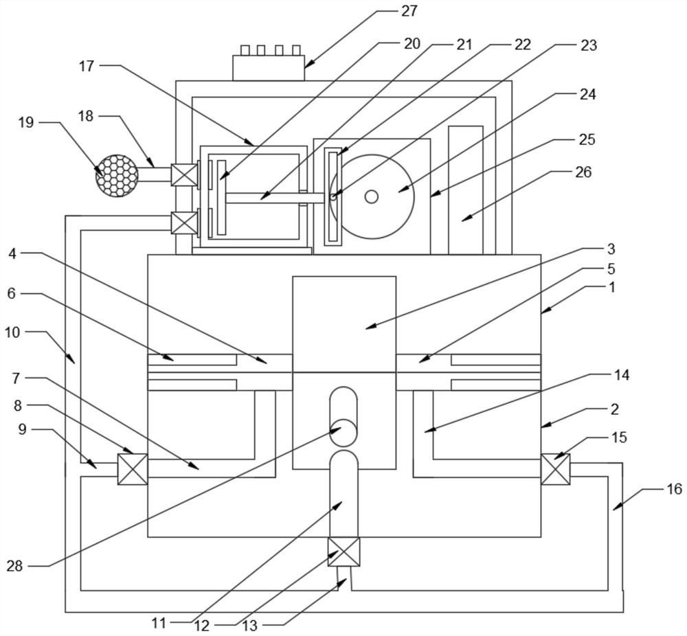
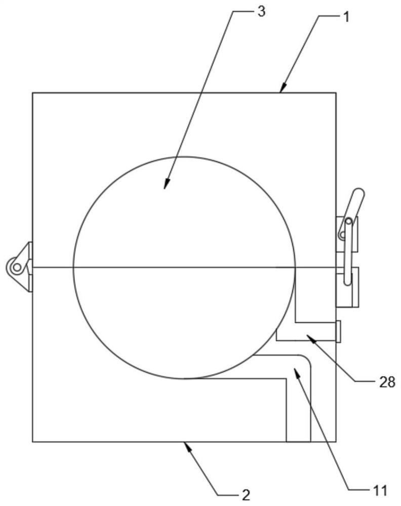
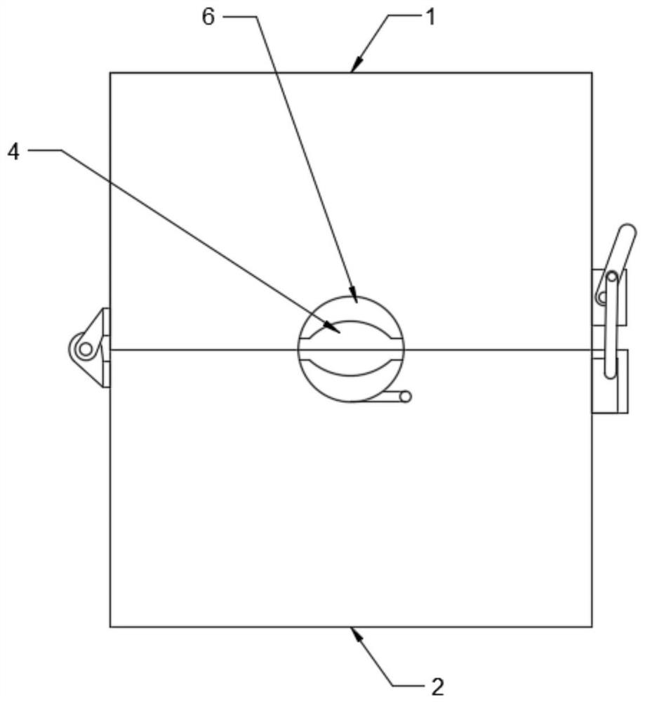
[0020] see Figure 1-4 , in an embodiment of the present invention, an automatic wire breaker, including a junction box; It is fixedly connected by a lock; a columnar spinning cavity 3 is formed between the upper box body 1 and the lower box body 2, the left side of the spinning cavity 3 is connected with a left clamping channel 4, and the right side of the spinning cavity 3 is connected There is a right clamping channel 5, a rubber gasket 6 is bonded in the left clamping channel 4 and the right clamping channel 5, which is convenient for squeezing and clamping the spinning thread; specifically, when the spinning thread breaks, open the upper Box body 1, place the broken part of the broken spinning thread in the spinning chamber 3, nest the outer ends of the spinning thread in the left clamping channel 4 and the right clamping channel 5 respectively, close the upper box body 1 , lock the lock.

[0021] The lower part of the spinning chamber 3 is connected with a central air ...

Embodiment 2

[0026] The difference between this embodiment and Embodiment 1 is that in order to fully disperse the spun yarn into fiber bundles, the inside of the left clamping channel 4 is tangentially connected with a left air inlet channel 7, and the left air inlet channel 7 is connected with a first branch pipe 9. The first branch pipe 9 communicates with the intake main pipe 10, and the first solenoid valve 8 is provided at the connection between the left intake passage 7 and the first branch pipe 9, and the first solenoid valve 8 is connected with the switch plate 27 to facilitate the opening of the first solenoid valve 8. Make the air flow enter the left clamping channel 4, and swirl and blow off the spinning yarn, so that the spinning yarn is dispersed into scattered fiber bundles; similarly, the inside of the right clamping channel 5 is tangentially connected to the right air inlet channel 14. The right air intake channel 14 is connected with a third branch pipe 16, and the third b...


PUM


Abstract

The invention discloses an automatic splicing device for broken yarns. The automatic splicing device for broken yarns comprises a yarn splicing box, wherein the yarn splicing box comprises an upper box body and a lower box body which are hinged through a hinge, and the front sides of the upper box body and the lower box body are fixedly connected through lock catches; a columnar spinning cavity isformed between the upper box body and the lower box body, the left side of the spinning cavity communicates with a left clamping channel, and the right side of the spinning cavity communicates with aright clamping channel. The lower part of the spinning cavity tangentially communicates with a central air inlet channel. Through the arrangement of the yarn splicing box comprising the upper box body and the lower box body which are hinged to each other and provided with the lock catches, the spinning cavity, the left clamping channel, the right clamping channel, a rubber gasket, the central airinlet channel and an air blowing cylinder, clamping and wiring of doubling threads are achieved, carrying is convenient, and operation is easy and convenient; by arranging the left air inlet channel,the right air inlet channel, a first electromagnetic valve, a second electromagnetic valve and a third electromagnetic valve, doubling threads are blown away into fiber bundles to facilitate .

Description

technical field [0001] The invention relates to the field of textile equipment, in particular to an automatic wire breaker. Background technique [0002] During the spinning process, the spinning yarn is prone to breakage and needs to be wired. The traditional wiring device has a complicated structure and is inconvenient to hold and carry. Contents of the invention [0003] The object of the present invention is to provide an automatic wire breaker to solve the problems raised in the background art above. [0004] To achieve the above object, the present invention provides the following technical solutions: [0005] An automatic wire breaker, including a junction box; the junction box includes an upper box body and a lower box body hinged by a hinge, and the front side of the upper box body and the lower box body are fixedly connected by a lock; the upper box body A columnar spinning cavity is formed between the box body and the lower box body, the left side of the spinn...

Claims


Application Information

Patent Timeline
Patent Type & Authority Applications(China)
IPC IPC(8): D01H15/00
CPCD01H15/00
Inventor 陈明
Owner 吴江兴宇经编有限公司
Why Eureka
Try Eureka