
Automatic collecting device and automatic collecting method for worm tooth

A technology of automatic collection and worm teeth, which is applied in the direction of conveyor control devices, transportation and packaging, loading/unloading, etc., can solve problems such as low efficiency, machine bruises, and high degree of subjective influence, so as to improve safety and work efficiency , easy to organize, simple structure effect

Pending Publication Date: 2020-10-16
华宏达精密五金制造(深圳)有限公司
View PDF0 Cites 1 Cited by
  • Summary
  • Abstract
  • Description
  • Claims
  • Application Information

AI Technical Summary

Problems solved by technology

[0003] In the existing technology, the workpieces are usually arranged in an orderly manner on the fixture of the inspection or machining center manually, and there is no automatic receiving mechanism connected with the fixture
Manual receiving is subject to a relatively large degree of subjective influence, it is not easy to grasp the time of receiving materials, the efficiency is low, and the safety of operators cannot be effectively guaranteed, and there are often situations of being injured by machines, which can no longer meet the production requirements of modern enterprises

Method used


Image

  • Automatic collecting device and automatic collecting method for worm tooth
  • Automatic collecting device and automatic collecting method for worm tooth
  • Automatic collecting device and automatic collecting method for worm tooth

Examples


Embodiment Construction

[0031] In order to fully understand the technical content of the present invention, the technical solutions of the present invention will be further introduced and illustrated below in conjunction with specific examples, but not limited thereto.

[0032] The following will clearly and completely describe the technical solutions in the embodiments of the present invention with reference to the accompanying drawings in the embodiments of the present invention. Obviously, the described embodiments are only some, not all, embodiments of the present invention. Based on the embodiments of the present invention, all other embodiments obtained by those skilled in the art without creative efforts fall within the protection scope of the present invention.

[0033] In describing the present invention, it is to be understood that the terms "center", "longitudinal", "transverse", "length", "width", "thickness", "upper", "lower", "front", " Orientation or position indicated by "back", "left...


PUM


Abstract

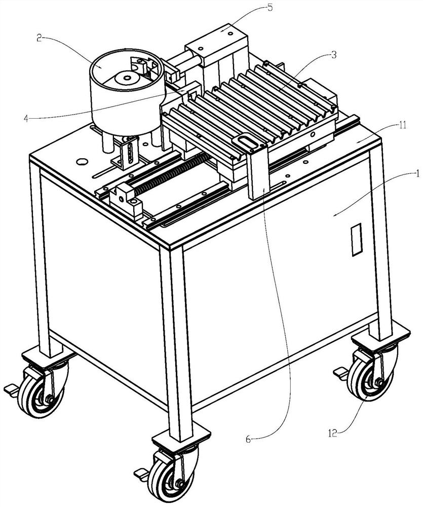
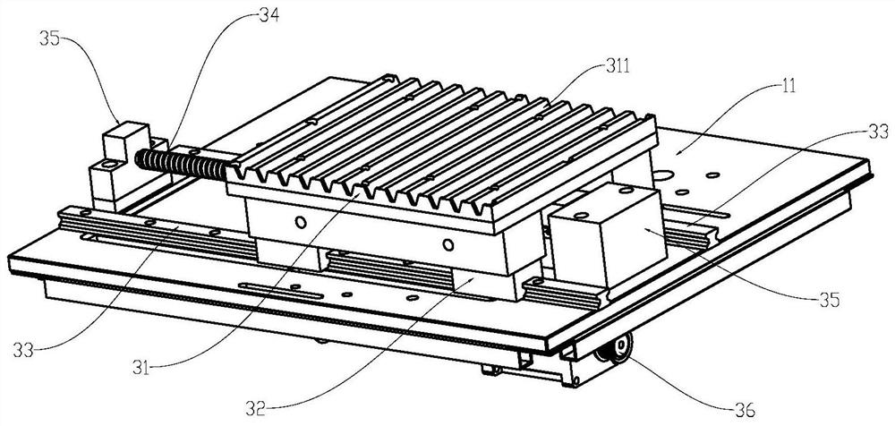
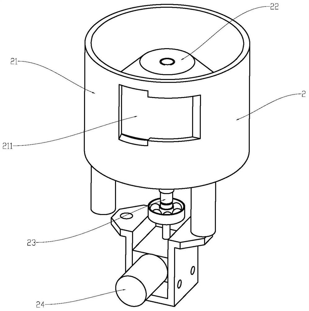
The invention discloses an automatic collecting device and automatic collecting method for a worm tooth. The device comprises a material distributing component, a material passing block, a material pushing component and a material receiving component, wherein the material distribution component comprises a turntable, a turntable shaft, a fence and a turntable motor; the fence is fixed on the periphery of the turntable; one end of the turntable shaft is connected with the turntable, the other end of the turntable shaft is connected with the turntable motor, and the fence is provided with a discharge port; the material passing block is provided with a material passing groove corresponding to the position of the discharge port; the material pushing component comprises a material pushing cylinder, a material pushing sliding block, a material pushing guide rail and a material pushing hook; the material pushing guide rail is fixed on the material passing block, the material pushing slide block is slidably connected on the material pushing guide rail, the material pushing hook is fixedly connected with the material pushing sliding block, and the material pushing cylinder is connected withthe material pushing hook and can drive the material pushing hook to move in the length direction of the material pushing guide rail; the material pushing hook is provided with a hook part, and the hook part is arranged in the material passing groove; the receiving component comprises a receiving disc; and the material receiving disc is provided with a transverse groove, and the length directionof the transverse groove is the same as the length direction of the material passing groove. According to automatic collecting device and automatic collecting method for the worm tooth, the safety andthe working efficiency are improved.

Description

technical field [0001] The invention relates to the field of mechanical automation, and more specifically relates to an automatic collection device and an automatic collection method for worm teeth. Background technique [0002] The worm tooth is a transmission part commonly used in the prior art. It has the characteristics of small size, high precision and low surface roughness. The fixture of the machining center has always been a difficult technical problem to solve. The enterprise hopes to use a material receiving mechanism suitable for the shape, characteristics and weight of the workpiece, so as to improve the detection or processing efficiency of worm teeth. [0003] In the existing technology, the workpieces are usually arranged in an orderly manner on the fixture of the inspection or machining center manually, and there is no automatic material receiving mechanism connected with the fixture. Manual receiving is subject to a relatively large degree of subjective in...

Claims


Application Information

Patent Timeline
Patent Type & Authority Applications(China)
IPC IPC(8): B65G65/44B65G43/00
CPCB65G43/00B65G65/44
Inventor 肖斌农严寒张小波
Owner 华宏达精密五金制造(深圳)有限公司
Learn More