Double-roller based reverse rotation type feed stirring equipment and stirring method thereof
A technology of reverse rotation and feed mixing, applied in feed, mixing methods, mixer accessories, etc., can solve the problems of reduced service life, slow mixing speed of single drum, and sufficient mixing of food and water.
- Summary
- Abstract
- Description
- Claims
- Application Information
AI Technical Summary
Problems solved by technology
Method used
Image
Examples
Embodiment 1
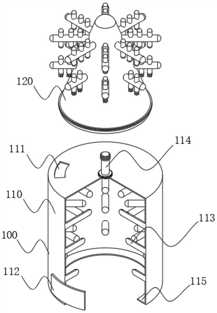
[0066] see Figure 1-Figure 10 as well as Figure 11 with Figure 12 As shown, a double-drum counter-rotating feed mixing device is provided, including a stirring device 100, a support protection device 200 and a transmission device 300 arranged inside the support protection device 200. The stirring device 100 includes at least an outer drum 110, and the outer drum 110 The position near the outer edge of the top is provided with a material inlet 111, which is used for feeding into the outer drum 110, and the bottom of the front side of the outer drum 110 is provided with a discharge bin door 112, which is opened after the stirring is completed To collect the stirred feed, the bottom of the rear side of the discharge bin door 112 is provided with a limit plate 115, the limit plate 115 is rotatably connected in the limit groove 122, and the top of the limit groove 122 is provided with an inner drum 120 to support and protect The device 200 includes a protective frame 210, the ...
Embodiment 2
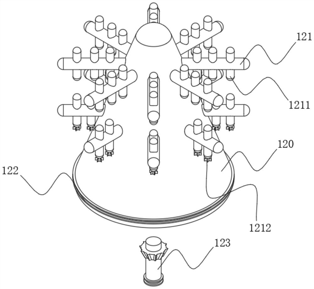
[0079] In order to make the feed more fully during the mixing process, improve the mixing quality, and reduce the damage to the feed during mixing, please refer to image 3 As shown, the inner drum 120 adopts a conical design, and the conical design makes the feed slide down to the edge of the bottom of the inner drum 120 under the action of gravity, which is convenient for collection after stirring.
[0080] Specifically, the inner stirring rod 121 is inserted with a disturbing flow rod 1211, and the disturbing rod 1211 prevents the inner stirring rod 121 and the outer stirring rod 113 from generating a vortex during the stirring process through its own resistance, so as to prevent the vortex from affecting the stirring quality.
[0081] In addition, the ends of the outer stirring rod 113, the inner stirring rod 121 and the spoiler rod 1211 all adopt a spherical design, and the spherical design makes the ends of the outer stirring rod 113, the inner stirring rod 121 and the sp...
Embodiment 3
[0083] See Figure 14 As shown, the bottom of the spoiler rod 1211 at the bottom is provided with a spoiler fan 1212, and the spoiler fan 1212 includes at least:
[0084] A spoiler rotating shaft 1213, the spoiler rotating shaft 1213 is used to rotate and connect with the spoiler rod 1211, and a disturbing flow slot 1214 is opened around the spoiler rotating shaft 1213;
[0085] The spoiler fan blade 1215, the spoiler fan blade 1215 is plugged with 1214 and the spoiler slot 1214, and the end of the spoiler fan blade 1215 close to the spoiler slot 1214 is provided with a through hole 1216;
[0086] Fixed bolt 1217, fixed bolt 1217 is used to pass through the through hole 1216, and is threadedly connected with the inner wall of the spoiler slot 1214, the spoiler fan blade 1215 is driven by the feed resistance to rotate the spoiler rotating shaft 1213, and the spoiler fan 1213 rotates during the rotation process. The leaf 1215 acts on the feed through the reaction force, so as t...
PUM
 Abstract
Description
Claims
Application Information
 - Generate Ideas
- Intellectual Property
- Life Sciences
- Materials
- Tech Scout
- Unparalleled Data Quality
- Higher Quality Content
- 60% Fewer Hallucinations
Browse by: Latest US Patents, China's latest patents, Technical Efficacy Thesaurus, Application Domain, Technology Topic, Popular Technical Reports.
© 2025 PatSnap. All rights reserved.Legal|Privacy policy|Modern Slavery Act Transparency Statement|Sitemap|About US| Contact US: help@patsnap.com


