Rotary adjustable raw material culture equipment for cosmetic production
A cultivation equipment and adjustable technology, applied in the field of rotary adjustable raw material cultivation equipment for cosmetic production, can solve the problems of non-irradiation, limited application scope, uneven growth of plant tissues, etc., to meet the needs of oxygen and meet different needs , the effect of accelerating the flow velocity
- Summary
- Abstract
- Description
- Claims
- Application Information
AI Technical Summary
Problems solved by technology
Method used
Image
Examples
Embodiment 1
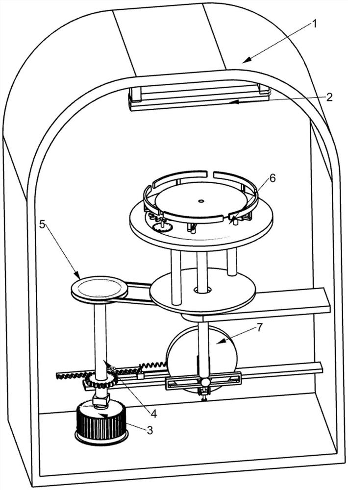
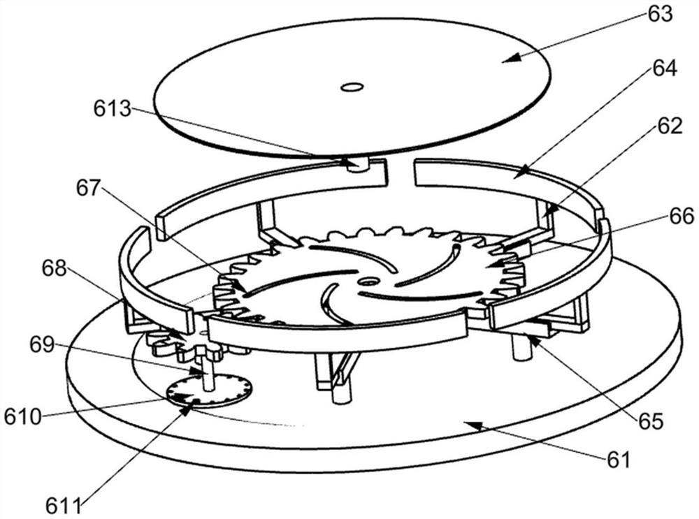
[0024] A rotary adjustable raw material cultivation equipment for cosmetic production, such as Figure 1-8 As shown, it includes an installation shell 1, an LED lamp 2, a servo motor 3, a first rotating shaft 4, a rotating mechanism 5 and a fixing mechanism 6, and the LED lamp 2 for providing light source for plant tissue culture is fixedly installed in the installation shell 1 on the bottom side of the top, the servo motor 3 is fixedly installed on the upper side of the bottom of the installation shell 1, the first rotating shaft 4 is fixed on the output shaft of the servo motor 3, and the rotating mechanism 5 is installed on the first rotating shaft On the shaft 4 and the mounting shell 1, the fixing mechanism 6 is mounted on the rotating mechanism 5.
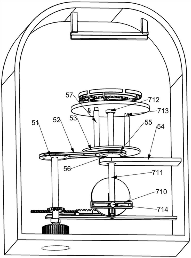
[0025] Specifically, such as Figure 1-2 As shown, the rotating mechanism 5 includes a first pulley 51, a connecting belt 52, a rotating disc 53, a mounting plate 54, a second pulley 55, a first bearing 56 and a guide rod 57...
Embodiment 2
[0029] On the basis of Embodiment 1, such as Figure 1-2 with Figure 5 As shown, it also includes the lifting mechanism 7 for driving the placement tray 63 to move up and down. The lifting mechanism 7 is installed on the first rotating shaft 4 and the installation shell 1 and connected with the fixing mechanism 6. The lifting mechanism 7 Including second pinion 71, first rack 72, horizontal plate 73, slide rail 74, slider 75, second rack 76, third pinion 77, second rotating shaft 78, connecting disc 79, connecting frame 710, lifting rod 711, second bearing 712, movable rod 713 and roller 714, the second pinion 71 is fixedly installed on the first rotating shaft 4 and located above the servo motor 3, and the horizontal plate 73 is fixedly installed On one side inside the installation shell 1 and below the installation plate 54, the slide rail 74 is fixedly installed on the upper side of the horizontal plate 73 and is close to the first rotating shaft 4, and the slide block 75...
Embodiment 3
[0032] On the basis of Example 2, such as Figure 6-7 As shown, it also includes an adjustment mechanism 8 for adjusting the distance between the placement plate 63 and the LED lamp 2. The adjustment mechanism 8 is installed on the connection disc 79. The adjustment mechanism 8 includes a fixing nut 81, a moving Screw rod 82, guide block 83 and guide plate 84, described fixed nut 81 is fixedly installed on one side of connection disc 79 and is positioned at the below of roller 714, and described moving screw rod 82 is installed in the threaded hole of fixed nut 81 by thread , one side of the connecting disc 79 is fixedly installed with two parallel guide plates 84, the guide block 83 is slidably installed on the two guide plates 84 and the guide block 83 is connected with the upper end of the moving screw 82 in a rotational manner, the The moving screw 82 is used to drive the guide block 83 to slide up and down, and one end of the roller 714 is fixedly connected to the guide b...
PUM
 Abstract
Description
Claims
Application Information
 - R&D
- Intellectual Property
- Life Sciences
- Materials
- Tech Scout
- Unparalleled Data Quality
- Higher Quality Content
- 60% Fewer Hallucinations
Browse by: Latest US Patents, China's latest patents, Technical Efficacy Thesaurus, Application Domain, Technology Topic, Popular Technical Reports.
© 2025 PatSnap. All rights reserved.Legal|Privacy policy|Modern Slavery Act Transparency Statement|Sitemap|About US| Contact US: help@patsnap.com


