
Pump unit

A pump unit and pump body technology, which is applied in the field of circulating pumps, can solve the problems of complex pump unit structure, complex assembly process, and long assembly time, and achieve the effects of saving raw material costs, high space utilization, and simple structure

Pending Publication Date: 2020-10-13
HEFEI XINHU CANNED MOTOR PUMP
View PDF0 Cites 0 Cited by
  • Summary
  • Abstract
  • Description
  • Claims
  • Application Information

AI Technical Summary

Problems solved by technology

This kind of pump unit has a large volume and is not suitable for the environment with limited installation space, and the structure of the pump unit is complicated, which makes the assembly process complicated and the assembly time is long

Method used


Image

  • Pump unit
  • Pump unit
  • Pump unit

Examples


Embodiment Construction

[0033] The specific implementation manners of the present invention will be described in further detail below in conjunction with the embodiments and accompanying drawings. Here, the following examples of the present invention are used to illustrate the present invention, but not to limit the scope of the present invention.

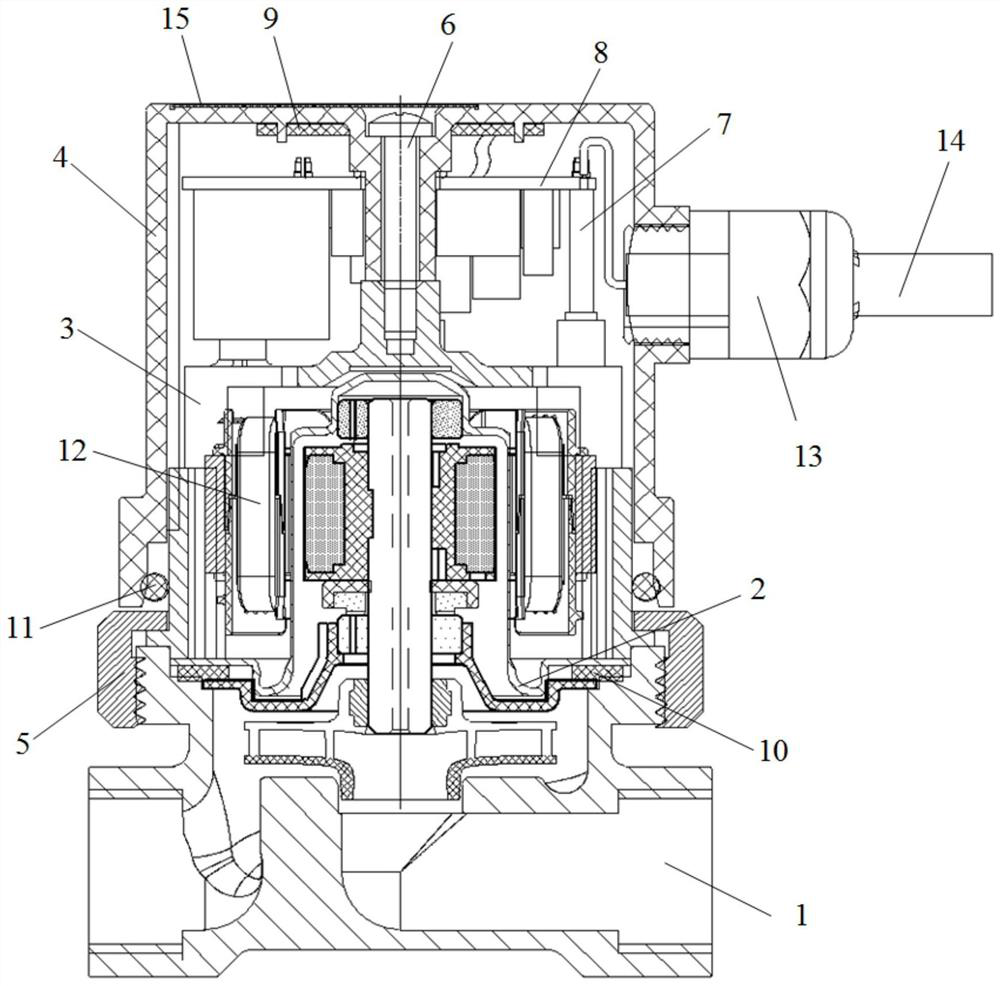
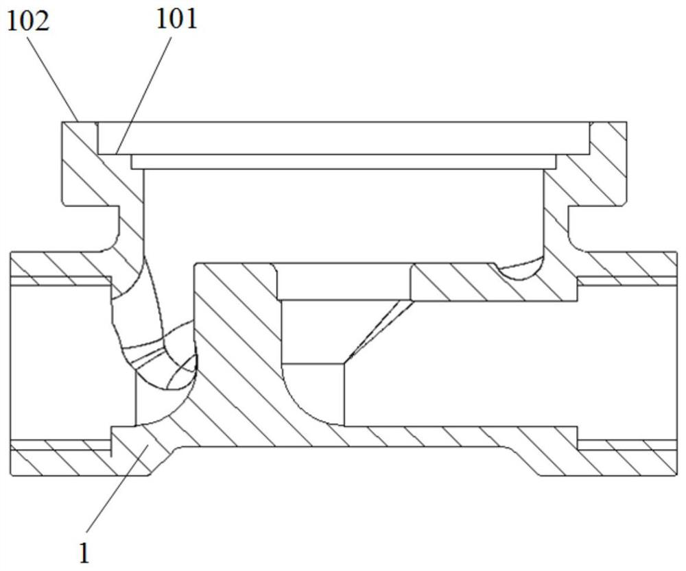
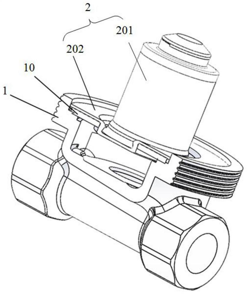
[0034] Such as figure 1 As shown, a pump unit provided by an embodiment of the present invention includes: a pump body 1 , a stator shielding sleeve 2 , a motor housing 3 and a junction box housing 4 . The pump body 1 is arranged at the bottom of the pump unit; figure 2 and image 3 As shown, the stator shielding sleeve 2 is arranged above the pump body 1, the upper part of the stator shielding sleeve 2 is a cylindrical part 201 with an open lower end, and the cylindrical part 201 is set on the outside of the rotor; the bottom of the cylindrical part 201 is along its radial direction A flange portion 202 is arranged outwardly, and the flange portion 2...


PUM


Abstract

The invention relates to a pump unit. The pump unit comprises a pump body, a stator shield sleeve, a motor shell and a junction box shell. The stator shield sleeve is arranged above the pump body, theupper portion of the stator shield sleeve is a cylindrical part with an opening in the lower end, and the bottom of the cylindrical part is outwards provided with a flanging part placed on the spigotface of the pump body in the radial direction. The motor shell is in a cylindrical shape with an opening in the lower end, the stator shield sleeve is covered with the motor shell, and the stator shield sleeve is arranged on the upper end face of the pump body through a boss on the outer side of the side wall of the stator shield sleeve. The junction box shell is in a cylindrical shape with an opening in the lower end, the junction box shell covers the motor shell, and the function box shell is connected with the motor shell through bolts. The pump unit is simple and compact in structure, high in space utilization rate, reliable in connection between components and convenient to assemble. The junction box shell wraps the motor shell, so that the motor shell does not need paint spraying, the surface does not need to be subjected to shot blasting treatment, production procedures are reduced, the raw material cost is saved, and the production efficiency is improved.

Description

technical field [0001] The invention relates to the technical field of circulating pumps, in particular to a pump unit. Background technique [0002] The operating environment of the circulation pump is complex and the installation space is limited. In the current circulating pumps, the driving motor is arranged in the stator housing, and the axial end of the stator housing is provided with a junction box, and the electronic components of the driving motor are arranged in the junction box, so that the pump components can achieve different functions in different embodiments. . This kind of pump unit has a large volume and is not suitable for an environment with limited installation space, and the structure of the pump unit is complicated, which makes the assembly process complicated and the assembly time is long. Contents of the invention [0003] (1) Technical problems to be solved [0004] The object of the present invention is to provide a pump unit with simple and co...

Claims


Application Information

Patent Timeline
Patent Type & Authority Applications(China)
IPC IPC(8): F04D13/06H02K5/04H02K5/22
CPCF04D13/0606F04D13/0693H02K5/04H02K5/225
Inventor 韩元平章立何燕王于宽
Owner HEFEI XINHU CANNED MOTOR PUMP
Learn More