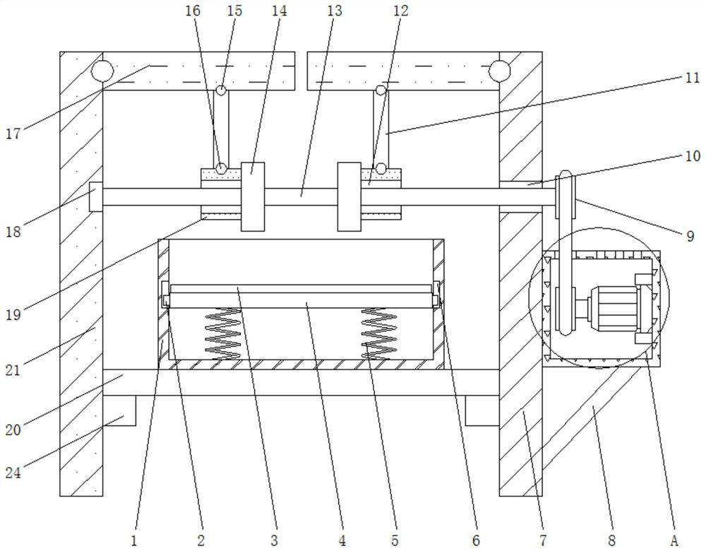
Lead frame electroplating and discharging device

A technology of lead frame and vertical plate, which is applied in the field of lead frame electroplating and blanking device, can solve problems affecting the production efficiency of circuit boards, and achieve the effects of avoiding inconvenience, preventing production efficiency, and avoiding damage

Pending Publication Date: 2020-10-13
泰兴市龙腾电子有限公司
View PDF6 Cites 3 Cited by
  • Summary
  • Abstract
  • Description
  • Claims
  • Application Information

AI Technical Summary

Problems solved by technology

[0003] The present invention provides and aims to solve the above-mentioned problems affecting the production efficiency of circuit boards

Method used


Image

  • Lead frame electroplating and discharging device
  • Lead frame electroplating and discharging device
  • Lead frame electroplating and discharging device

Examples


Embodiment Construction

[0017] In order to make the object, technical solution and advantages of the present invention clearer, the present invention will be further described in detail below in conjunction with the accompanying drawings and embodiments. It should be understood that the specific embodiments described here are only used to explain the present invention, not to limit the present invention.

[0018] In describing the present invention, it should be understood that the terms "length", "width", "upper", "lower", "front", "rear", "left", "right", "vertical", The orientation or positional relationship indicated by "horizontal", "top", "bottom", "inner", "outer", etc. are based on the orientation or positional relationship shown in the drawings, and are only for the convenience of describing the present invention and simplifying the description, rather than Nothing indicating or implying that a referenced device or element must have a particular orientation, be constructed, and operate in a ...


PUM


Abstract

The invention discloses a lead frame electroplating and discharging device which comprises a first vertical plate. A second vertical plate is arranged on the left side of the first vertical plate; support plates are fixedly connected to one side faces, close to each other, of the first vertical plate and the second vertical plate; sliding plates are fixedly hinged to one side faces, close to eachother, of the first vertical plate and the second vertical plate through two hinges; connecting rods are fixedly hinged to the bottom faces of the two sliding plates through two first pin shafts; andmoving blocks are fixedly hinged to the bottom ends of the two connecting rods through two second pin shafts. According to the lead frame electroplating and discharging device, a spring is arranged, acircuit board fallen from a sloping plate is sprung by utilizing the contractility of the spring, then the spring drives the sloping plate to move up and down and drives a sliding block to slide up and down, and the circuit board is then slid out of a collection box through a discharge hole so as to be protected conveniently during discharging, so that the problems that during discharging, the circuit board is damaged and the production efficiency of the circuit boards is influenced are solved.

Description

technical field [0001] The invention belongs to the field of circuit boards, in particular to a lead frame electroplating blanking device. Background technique [0002] The names of circuit boards include ceramic circuit boards, alumina ceramic circuit boards, aluminum nitride ceramic circuit boards, circuit boards, PCB boards, aluminum substrates, high-frequency boards, thick copper boards, impedance boards, PCBs, ultra-thin circuit boards, ultra-thin Circuit boards, printed circuit boards, etc., circuit boards make circuits miniaturized and intuitive, and play an important role in mass production of fixed circuits and optimizing the layout of electrical appliances. Circuit boards can be called printed circuit boards or printed circuit boards. With the development of society Development, household electrical appliances generally have their own circuit boards. At this stage, circuit boards need lead frames in the production process. However, lead frame electroplating and bla...

Claims


Application Information

Patent Timeline
Patent Type & Authority Applications(China)
IPC IPC(8): C25D17/00
CPCC25D17/00
Inventor 陈虎殷旭陈惠
Owner 泰兴市龙腾电子有限公司
Why Eureka
Try Eureka