
Patsnap Eureka
For R&D, Patsnap Eureka makes reading and utilizing patents & technical documents easy.
Patsnap Eureka AIR
Designed for self-driven R&D workflows. Generate viable solutions, solve complex R&D challenges, empower your innovation with AI.

Patsnap Eureka Materials
Designed for material experts only. Revolutionize your material R&D, from search, analyze, to developing new materials.

TechResearch
Generate reliable direction feasibility study reports for your R&D in just a few steps.

TechSeek
Discover and master advanced knowledge NOW. Basics, ideas, possibilities, all at once.

TechMind
As an expert in R&D Theories, TechMind can generates customized viable solutions instantly.

TechRisk
Analyze your overall solution with one click, know your potential R&D risks in advance.

TechMonitor
Get weekly tech updates, stay abreast of the latest tech innovations and key insights.
Automatic board turnover device for flexible circuit board spray printing machine
A technology for flexible circuit boards and inkjet printers, applied in printing devices, printing and other directions, can solve the problems of time-consuming and labor-intensive, low accuracy of manual turning over positioning, etc., to simplify the process flow, save the conversion and positioning, and reduce the floor space. Effect
- Summary
- Abstract
- Description
- Claims
- Application Information
AI Technical Summary
Problems solved by technology
Method used
Image

Examples
Embodiment 1
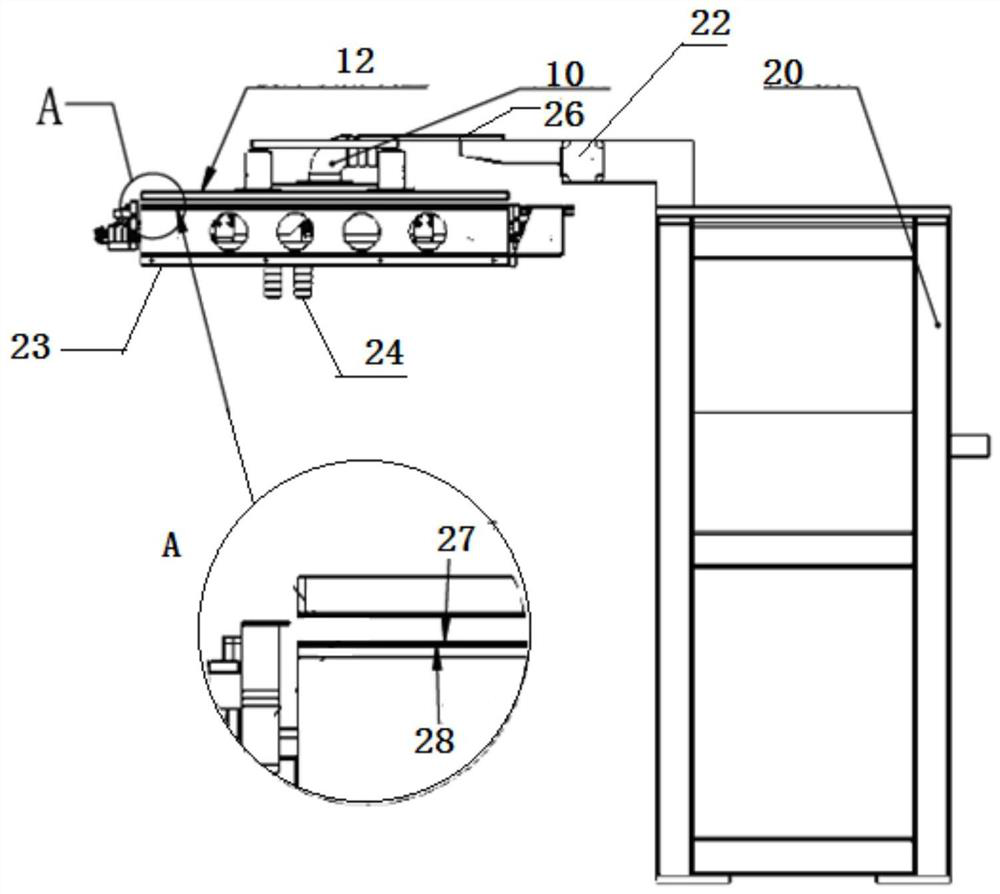
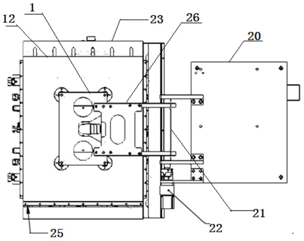
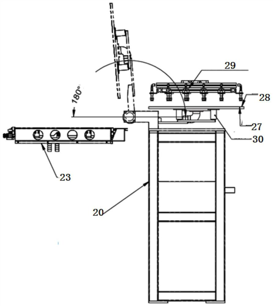
[0032] An automatic turning device for a flexible circuit board printing machine, comprising a turning mechanism bracket 20 arranged on one side of the flexible circuit board printing machine 23, driven by a turning motor 22 on the turning mechanism bracket 20 The rotating shaft 21, the positioning plate 1 fixed on the rotating shaft 21 through the connecting piece 26, and the adsorption platform 12 arranged at the bottom of the positioning plate 1 through the buffer assembly 30;
[0033] Wherein, the buffer assembly includes a guide sleeve 2 fixed on the upper surface of the adsorption platform and a spring guide column 3 that moves up and down in the inner cavity of the guide sleeve 2; wherein the top end of the spring guide column 3 is fixed on the On the positioning plate 1, the upper outer edge of the spring guide column 3 is fixedly provided with an upper limiter 4 to form a support for the guide sleeve 2 in the overturned state, and the lower outer edge of the spring gui...
Embodiment 2
[0040] In this embodiment, on the basis of Embodiment 1, the shape and number of each component are optimized.
[0041] As a preferred manner, the positioning plate 1 is a rectangular plate, and the top end of the spring guide post 3 is fastened to the positioning plate 1 by screws. Simple structure, easy to assemble and assemble.
[0042] As a preferred manner, there are four buffer assemblies, which are respectively symmetrically arranged at four corners of the bottom of the positioning plate 1 . The symmetrically arranged structure makes the stress between the adsorption platform and the turnover plate more uniform.
[0043] As a preferred manner, the upper limit member 4 and the lower limit member 5 are respectively limit rings fixed on the upper and lower ends of the outer wall of the spring guide post 3 . The annular structure has a large stress surface.
Embodiment 3
[0045] In this embodiment, on the basis of Embodiment 1, the adsorption platform 12 is further improved.
[0046] The adsorption platform 12 includes a microporous plate 7 forming an adsorption surface, a boss 8 fixed on the top of the micropore plate 7 and an adsorption bottom plate 9 supported by the boss 8, wherein the upper part of the adsorption bottom plate 9 is Fitted with a pipe joint 10, the combination of the pipe joint 10, the groove formed between the bosses 8 and the microholes formed on the micropore plate 7 forms an airflow channel.
[0047] Way of working:
[0048] The suction fan is connected to the pipe joint 10 through a pipeline, and negative pressure is generated through the airflow channel. Since the micropores are densely covered with micropores, even if the sucked object (such as a flexible circuit board) does not cover the entire surface of the micropores, the negative pressure lost The pressure is still less, and enough negative pressure can be gener...
PUM
 Abstract
Description
Claims
Application Information
 - R&D Engineer
- R&D Manager
- IP Professional
- Industry Leading Data Capabilities
- Powerful AI technology
- Patent DNA Extraction
Browse by: Latest US Patents, China's latest patents, Technical Efficacy Thesaurus, Application Domain, Technology Topic, Popular Technical Reports.
© 2024 PatSnap. All rights reserved.Legal|Privacy policy|Modern Slavery Act Transparency Statement|Sitemap|About US| Contact US: help@patsnap.com