BMS function safety control system and method

A technology for functional safety and control systems, applied in cell structure combinations, electric vehicles, electrical components, etc., can solve the problems of safety function failure, poor execution effect, poor controllability, etc., and achieve the effect of reducing the risk of execution errors.

Pending Publication Date: 2020-10-09
SHANGHAI JINMAI ELECTRONICS TECH
View PDF0 Cites 2 Cited by
  • Summary
  • Abstract
  • Description
  • Claims
  • Application Information

AI Technical Summary

Problems solved by technology

In the existing BMS system design, for battery charging / discharging management, when the battery is overheated or overcharged or overdischarged, the BMS system needs to send a signal to disconnect the bus relay, but when the BMS system fails, it will cause this Safety function failure
Failure of the safety function may cause the actuator to perform incorrectly, resulting in a dangerous situation
[0003] When the existing BMS system manages battery charging / discharging, when one of the sensor acquisition circuit, communication circuit, and drive circuit fails, it may cause the normal execution function of the actuator to fail. Each system failure includes the failure of the component itself, the acquisition Errors, transmission errors, or instruction errors, etc., due to the simple collection of existing BMS systems, poor data identification certainty, single transmission path, and poor execution results, resulting in high failure rates and high identification execution failure rates, resulting in low functional safety levels. The probability of dangerous occurrence is high when failure fails, the coverage rate of safety mechanism is low, and the controllability is poor

Method used


Image

  • BMS function safety control system and method
  • BMS function safety control system and method
  • BMS function safety control system and method

Examples


Embodiment Construction

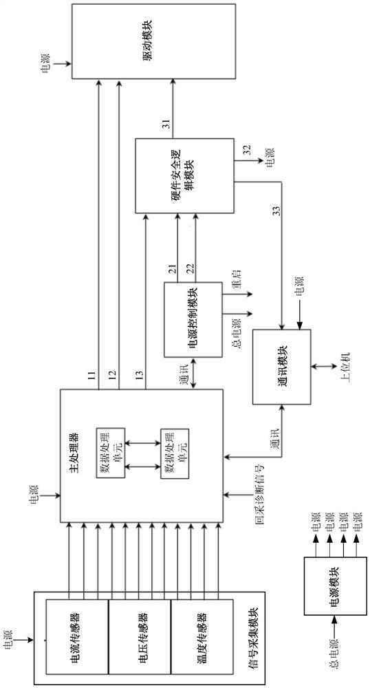
[0062] The present invention provides a BMS functional safety control system and control method in order to strengthen the realization of the safety protection of the BMS system and reduce the risk of actuator execution error due to the failure of the safety function of the BMS system. The following describes the invention with reference to the drawings and specific embodiments. Give further details.

[0063] See figure 1 As shown, a BMS functional safety control system includes:

[0064] A signal acquisition module for acquiring battery signals in a battery module (not shown);

[0065] The main processor, connected to the signal acquisition module, is used to determine whether the battery module is faulty based on the battery signal. If it is determined that no fault has occurred, it generates a maintenance drive instruction 11, and if it is determined that a fault has occurred, it generates a safe operation instruction ;

[0066] The power control module is used to receive the safe...


PUM


Abstract

The invention provides a BMS function safety control system and control method. The BMS function safety control system comprises a signal acquisition module for acquiring a battery signal, a main processor which is connected to the signal acquisition module and judges whether a battery module breaks down or not according to the battery signal, a power supply control module connected to the main processor, a hardware safety logic module connected to the power supply control module and the signal acquisition module, and a driving module connected to the main processor and the hardware safety logic module. When the battery module does not have a fault, the main processor generates a driving maintenance instruction to the driving module; when the battery module breaks down, the main processorgenerates a safe operation entering instruction to the power supply control module, and then the power supply control module generates a first hardware safety instruction to the hardware safety logicmodule, so that the hardware safety logic module controls the driving module to stop driving and turn off a corresponding power supply. According to the invention, the safety protection of the BMS system is enhanced, and the risk of execution errors is reduced.

Description

Technical field [0001] The present invention relates to the technical field of battery management, in particular to a BMS functional safety control system and control method. Background technique [0002] The BMS system needs to have safety functions in the application, and need to ensure functional safety when a fault occurs. The functional safety is related to the characteristics of the chip used, the software and hardware architecture and the circuit topology. At the same time, it also needs to consider the functional safety level achieved by the design. In the existing BMS system design, for battery charge / discharge management, when the battery is over-temperature or over-charged or over-discharged, the BMS system needs to send a signal to disconnect the bus relay, but when the BMS system fails, it will cause this The safety function fails. Failure of the safety function may lead to incorrect execution of the actuator, which may lead to dangerous situations. [0003] When the...

Claims


Application Information

Patent Timeline
IPC IPC(8): H01M10/42H02J7/00
CPCH01M10/425H02J7/00H01M2010/4271Y02E60/10
Inventor 吴文臣冉文邵庞朱春波
Owner SHANGHAI JINMAI ELECTRONICS TECH
Why Eureka
Try Eureka