Clamp type automatic mummified aphid collecting device
An automatic collection and clamping technology, which is applied in the direction of transportation and packaging, conveyors, animal husbandry, etc., can solve the problems of cumbersome operation, low degree of automation and low work efficiency, and achieve simple operation steps, high degree of automation, clamping long lasting effect
- Summary
- Abstract
- Description
- Claims
- Application Information
AI Technical Summary
Problems solved by technology
Method used
Image
Examples
Embodiment 1
[0027] Embodiment 1: The purpose of this embodiment is to provide a clamping type automatic aphid collecting device. For the structural defects of the existing equipment, it is troublesome to use, the operation steps are cumbersome, the degree of human intervention is large, and the degree of automation is low. The present invention A flow-type collection device is provided, which firstly processes the front side of the tobacco leaves, and then processes the back side without human intervention, and aims to improve the automation degree of tobacco leaf aphid collection.
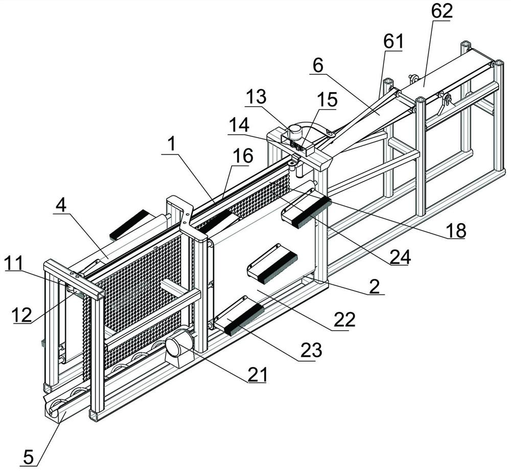
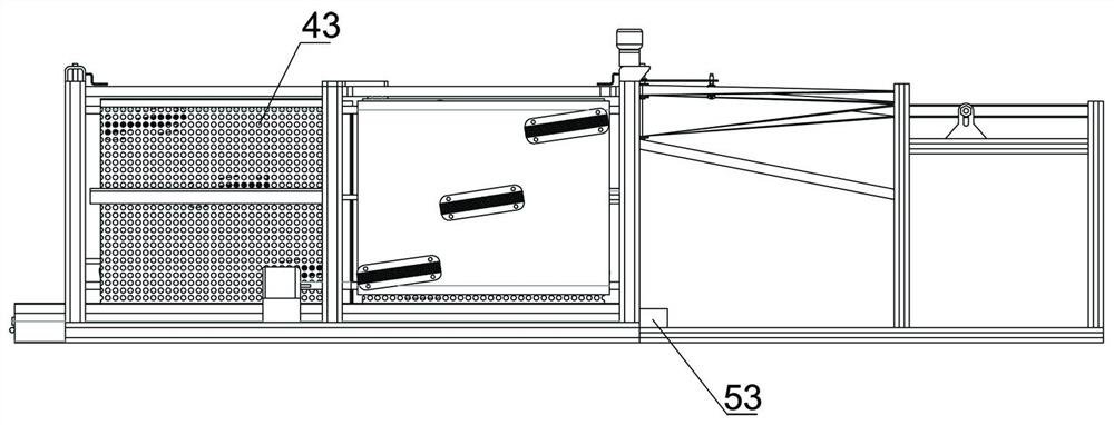
[0028] Such as Figure 1-4 As shown, the present invention provides a clamping type automatic collection device for aphids, comprising a tobacco leaf conveying mechanism 1, a aphid stripping mechanism and a collecting mechanism 5; the tobacco leaf conveying mechanism 1 includes a conveying motor 13, a The first conveyor belt 11 and the second conveyor belt 12 positioned at the left side of the frame are used ...
Embodiment 2
[0034] Embodiment 2: This embodiment is basically the same as Embodiment 1: the difference is that this embodiment also includes a feeding mechanism 6 .
[0035] First, the transmission gear set in this embodiment includes a first gear 14 and a second gear 15, the first gear 14 is connected to the rotating shaft of the conveying motor 13, the second gear 15 meshes with the first gear 14, and the first gear The rotating shafts of 14 and the second gear 15 are respectively connected with the driving shafts of the first conveyor belt and the second conveyor belt, thereby ensuring that the conveyor belts at the opposite places of the parallel first conveyor belt and the second conveyor belt have the same conveying direction.
[0036] Described feeding mechanism 6 comprises narrow feed belt 61 and wide feed belt 62; Described narrow feed belt 61 and wide feed belt 62 are arranged on the front end of frame, and the driving wheel of both passes through belt second gear and first gear ...
Embodiment 3
[0038] Embodiment 3: This embodiment is basically the same as Embodiment 1, the difference is that this embodiment further restricts the arrangement of the stripping brush 23 .
[0039] The stripping brush 23 is arranged at intervals on the outside of the roll surface of the first stripping roller 22 and the second stripping roller 32, thereby forming a front side stripping group, a middle stripping group and a rear side stripping group on the roller surface, each stripping group Set with 2-3 peeling brushes.
[0040] In this embodiment, the stripping brushes are set as the front side stripping group, the middle stripping group and the rear side stripping group, and the three groups of stripping brush groups can be arranged at intervals along the transverse direction or close to each other. By designing the rotating speed of the conveyor belt and the stripping brush roller, the front side The stripping group, the middle stripping group and the rear side stripping group all per...
PUM
 Abstract
Description
Claims
Application Information
 - R&D
- Intellectual Property
- Life Sciences
- Materials
- Tech Scout
- Unparalleled Data Quality
- Higher Quality Content
- 60% Fewer Hallucinations
Browse by: Latest US Patents, China's latest patents, Technical Efficacy Thesaurus, Application Domain, Technology Topic, Popular Technical Reports.
© 2025 PatSnap. All rights reserved.Legal|Privacy policy|Modern Slavery Act Transparency Statement|Sitemap|About US| Contact US: help@patsnap.com


