Mold release structure for four-angle core drawing of side face of air outlet shell

An air outlet and housing technology, which is applied in the field of the release structure of the four-angle core pulling on the side of the air outlet housing, can solve the problems of difficulty in designing the side of the air outlet housing, and achieves reduction in quantity, simplification of the assembly process, and reduction in manufacturing. cost effect

Active Publication Date: 2020-10-02
NINGBO JOYSONQUIN AUTOMOTIVE SYST HLDG CO LTD
View PDF3 Cites 0 Cited by
  • Summary
  • Abstract
  • Description
  • Claims
  • Application Information

AI Technical Summary

Problems solved by technology

[0004] Aiming at the technical problem that the side design of the air outlet housing is difficult in the prior art, the present invention provides a mold-removing structure with core-pulling at four angles on the side of the air outlet housing, which mechanically drives the slider through the mold opening force to realize a side Core pulling at four angles can realize core pulling on the side of the air outlet housing, and can form a dial assembly buckle, damper assembly hole and main blade assembly hole, making the assembly of parts simple

Method used


Image

  • Mold release structure for four-angle core drawing of side face of air outlet shell
  • Mold release structure for four-angle core drawing of side face of air outlet shell
  • Mold release structure for four-angle core drawing of side face of air outlet shell

Examples


Embodiment 1

[0036] combined with Figure 1-11 , a demoulding structure with four-angle core-pulling on the side of the air outlet housing in this embodiment, including a first slider seat 301, a second slider seat 310, a third slider seat 311, and a fourth slider seat 312 , the first slider insert 1, the second slider insert 2 and the third slider insert 3, the first slider seat 301 is slidably connected to the second slider seat 310 at one end, the second slider The other end of the seat 310 is fixedly connected with the fourth slider seat 312, the third slider seat 311 is located between the second slider seat 310 and the fourth slider seat 312, and the first slider insert 1 is fixed on On the third slider seat 311, the second slider insert 2 and the third slider insert 3 are fixed on the first slider seat 301, and the second slider insert 2 passes through the second Slider seat 310, the third slider seat 311 and the fourth slider seat 312, the third slider insert 3 passes through the ...

Embodiment 2

[0039] combined with Figure 9 and 11 , a demoulding structure with four-angle core-pulling on the side of the air outlet shell in this embodiment, compared with the technical solution of Embodiment 1, the relative sliding side of the first slider seat 301 and the second slider seat 310 A fifth slider insert 5 is provided, and the second slider seat 310 is provided with a groove 51 opposite to the fifth slider insert 5, and the groove width of the groove 51 is greater than the width of the fifth slider insert 5 .

[0040] A fifth slider insert 5 is provided on a side of the first slider seat 301 that slides relative to the second slider seat 310 , and a groove 51 is provided at a position opposite to the second slider seat 310 and the fifth slider insert 5 . The fifth slider insert 5 is a boss protruding from the surface of the first slider seat 301 , and the groove width of the groove 51 is larger than the width of the boss. When opening the mold, the first slider seat 301...

Embodiment 3

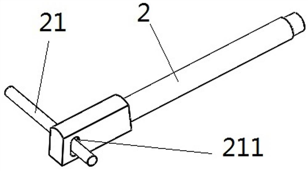
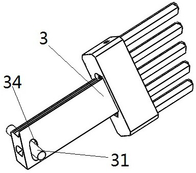
[0042] combined with Figure 2-5 , a demoulding structure with core-pulling at four angles on the side of the air outlet shell of this embodiment, compared with the technical solution of Embodiment 1 or 2, the second slider insert 2 is provided with a second positioning pin 21 and The first U-shaped hole 211, the third slider insert 3 is provided with a third positioning pin 31 and the second U-shaped hole 34, and the first slider seat 301 is respectively provided with a The first groove and the second groove of the piece 2 and the third slider insert 3, the second positioning pin 21 is set in the first groove, and the third positioning pin 31 is set in the second groove. The second slider insert 2 and the third slider insert 3 are respectively fixed on the first slider seat 301 through the second positioning pin 21 and the first U-shaped hole 211, the third positioning pin 31 and the second U-shaped hole 34. superior. When fixing, the second positioning pin 21 passes throug...


PUM


Abstract

The invention discloses a mold release structure for four-angle core drawing of the side face of an air outlet shell and belongs to the technical field of injection molds. The mold release structure comprises a first sliding block seat, a second sliding block seat, a third sliding block seat, a fourth sliding block seat, a first sliding block insert, a second sliding block insert and a third sliding block insert. The first sliding block seat is connected with one end of the second sliding block seat in a sliding manner, and the other end of the second sliding block seat is fixedly connected with the fourth sliding block seat. The third sliding block seat is located between the second sliding block seat and the fourth sliding block seat, the first sliding block insert is fixed to the thirdsliding block seat, and the second sliding block insert and the third sliding block insert are fixed to the first sliding seat. Specific to the technical problem that design of the side face of an airoutlet shell is difficult in the prior art, a sliding block is mechanically driven to achieve four-angle core drawing of one side face under the mold opening acting force, the air outlet shell side face, stirring wheel assembly buckles, an air door assembly hole and a main blade assembly hole can be formed, and part assembling is simple.

Description

technical field [0001] The invention relates to the technical field of injection molds, in particular to a demoulding structure with core-pulling at four angles on the side of an air outlet housing. Background technique [0002] The side features of the air outlet housing mainly include the dial assembly buckle, the damper assembly hole and the main blade assembly hole. The core pulling on the side of the air outlet housing involves these three features. At present, when the conventional air outlet shell is designed to be demolded, there will be one or two angles of core pulling on the side. The core-pulling direction on the side of the air outlet housing is mainly limited by four directions: the core-pulling direction on the side of the air outlet housing, the direction of the dial assembly buckle, the vector direction of the damper assembly hole and the vector direction of the main blade assembly hole, which makes the design of the air outlet housing difficult . If the d...

Claims


Application Information

Patent Timeline
Patent Type & Authority Applications(China)
IPC IPC(8): B29C45/40B29C45/33
CPCB29C45/33B29C45/4005
Inventor 倪晗王旭东
Owner NINGBO JOYSONQUIN AUTOMOTIVE SYST HLDG CO LTD
Why Eureka
Try Eureka