
Kinematic pair joint gap eliminating mechanism for feeding robot and implementation method of kinematic pair joint clearance eliminating mechanism

A joint gap and robot technology, applied in manipulators, program-controlled manipulators, manufacturing tools, etc., can solve the problems of simultaneous elimination, general use effect, and affecting the normal operation of equipment, so as to improve stability and durability and eliminate kinematic joints gap effect

Active Publication Date: 2020-10-02
安徽思卡瑞自动化工程有限公司
View PDF11 Cites 0 Cited by
  • Summary
  • Abstract
  • Description
  • Claims
  • Application Information

AI Technical Summary

Problems solved by technology

The existing method for eliminating joint clearance of kinematic joints is generally to install additional limit equipment on the outer wall of the equipment, but it may affect the normal operation of the equipment. At the same time, the existing method cannot eliminate the lateral clearance and radial clearance at the same time. Average effect

Method used


Image

  • Kinematic pair joint gap eliminating mechanism for feeding robot and implementation method of kinematic pair joint clearance eliminating mechanism
  • Kinematic pair joint gap eliminating mechanism for feeding robot and implementation method of kinematic pair joint clearance eliminating mechanism
  • Kinematic pair joint gap eliminating mechanism for feeding robot and implementation method of kinematic pair joint clearance eliminating mechanism

Examples


Embodiment approach

[0033]The implementation method of the kinematic pair joint gap elimination mechanism of the feeding robot includes the following steps:

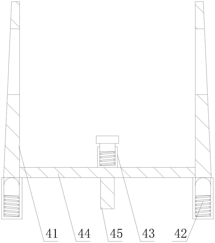
[0034] The first step: first install the first compensation structure 42 in the compensation assembly 4 at a predetermined position in the inner cavity of the base arm 3, wherein the first compensation structure 42 is symmetrically installed in the inner cavity of the base arm 3;

[0035] Step 2: install the remaining parts in the compensation assembly 4 in the inner cavity of the base arm 3, wherein it is necessary to ensure that the bottom surface of the compensation plate 41 is in contact with the first compensation structure 42, and after the entire compensation assembly 4 is installed, it must be ensured that it will not Affect the normal operation of the swing arm 1, the transverse circular shaft 2 and the base arm 3;

[0036] Step 3: Then install the swing arm 1 to the predetermined position, wherein the swing arm 1 needs to be froze...


PUM


Abstract

The invention discloses a kinematic pair joint gap eliminating mechanism for a feeding robot and an implementation method of the kinematic pair joint gap eliminating mechanism. A compensation assemblyis configured at the bottom end of a swing arm and used for compensating for abrasion generated after a swing arm runs for a long time, in this way, the swing arm and a basic arm can run stably for along time; and the inclined face of a compensation plate makes contact with the basic arm, original direct contact between the swing arm and the basic arm is replaced by installation of the compensation plate, and a first compensation structure jacks up the compensation plate to provide transverse compensation, so that left-right displacement possibly occurring to the swing arm is avoided, and the situation that the swing arm can rub against a transverse circular shaft to cause abrasion is avoided through radial compensation provided by a second compensation structure. Through the special design of the compensation plate, the first compensation structure and the second compensation structure, displacement of the swing arm after long-time operation can be avoided, a kinematic pair joint gap is effectively eliminated, and the operation stability and durability of equipment are greatly improved; and meanwhile the compensation assembly is arranged in an inner cavity of the equipment, sothat normal operation of a kinematic pair joint is not affected.

Description

technical field [0001] The invention relates to a kinematic sub-joint adjustment structure of a loading and unloading robot, in particular to a kinematic sub-joint gap elimination mechanism of a loading robot and an implementation method thereof. Background technique [0002] The loading and unloading robot can meet the requirements of "fast / mass processing cycle", "saving labor costs" and "improving production efficiency", and has become an ideal choice for more and more factories. A kinematic pair is an active connection in which two components are in direct contact and can produce relative motion. Elements such as points, lines, and surfaces that participate in the contact of two components and form a kinematic pair are called kinematic pair elements. At the junction of the kinematic joints of the loading and unloading robot, there are often different parts that cooperate, but after the parts are matched for a long time, their wear increases, and there is a gap at the ki...

Claims


Application Information

Patent Timeline
IPC IPC(8): B25J9/16B25J19/00
CPCB25J9/1641B25J19/00
Inventor 俞能超高大宏
Owner 安徽思卡瑞自动化工程有限公司
Learn More