
Chemical dissolving tank for sewage treatment and using method thereof

A technology of sewage treatment and dissolution tank, which is applied in the direction of dissolution, dissolution, and mixing methods, and can solve the problems of poor disinfection effect, difficult dissolution, and increased workload of stirring devices

Inactive Publication Date: 2020-10-02
陈燕娜
View PDF6 Cites 6 Cited by
  • Summary
  • Abstract
  • Description
  • Claims
  • Application Information

AI Technical Summary

Problems solved by technology

[0002] In the process of sewage treatment, the sewage needs to be precipitated, disinfected and filtered through multiple processes, so that the sewage can only be discharged when it meets the national discharge standard. During the disinfection process, it is necessary to add disinfectants to the sewage treatment tank, which is now common Disinfectants are all in the form of granules, which are not easy to dissolve when directly added, the disinfection effect is poor, and the time is long, so the disinfectant is usually dissolved to make it into a solution before adding
[0003] However, during the dissolution process, most treatment plants directly add the corresponding dose of chemicals into the dissolution tank, then inject water and stir it, and then discharge it to the sewage treatment tank. In the process of stirring and dissolving, it is generally necessary to use electrical equipment to drive Stirring will increase the operating cost of the dissolution tank. At the same time, in the process of adding chemicals, many drugs are added into the dissolution tank at one time for stirring, which will cause a large amount of drugs to accumulate in the dissolution tank, making the dissolution rate slower. , and the accumulation of medicaments is easy to block the water outlet, and more granular medicaments will increase the workload of the mixing device and easily damage the mixing equipment

Method used


Image

  • Chemical dissolving tank for sewage treatment and using method thereof
  • Chemical dissolving tank for sewage treatment and using method thereof
  • Chemical dissolving tank for sewage treatment and using method thereof

Examples


Embodiment Construction

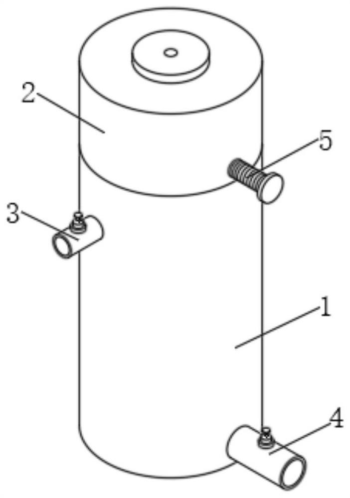
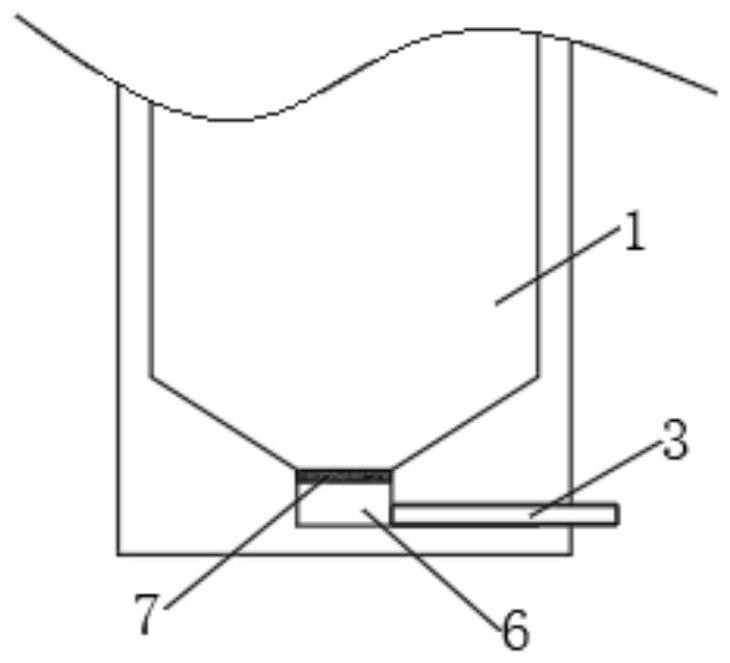
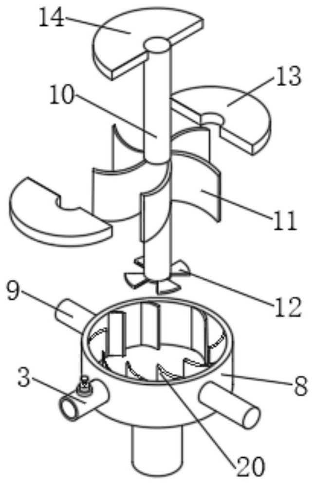
[0028] Embodiments of the present invention provide a chemical dissolving tank for sewage treatment and its use method, such as Figure 1-6 As shown, it includes a mixing box 1, the upper surface of the mixing box 1 is fixedly connected with a medicine warehouse 2, the top outer surface of the mixing box 1 is fixedly connected with a water inlet pipe 3, and the bottom outer surface of the mixing box 1 is fixedly connected with an outlet pipe 4, The outer surface of the medicament chamber 2 is movably clamped with the adjustment assembly 5, the water inlet pipe 3 extends to the interior of the mixing box 1 and is fixedly connected to the organic casing 8, the outer surface of the casing 8 is fixedly connected to the support rod 9, and the internal bearing of the casing 8 A rotating shaft 10 is connected, the outer surface of the rotating shaft 10 is fixedly sleeved with an impeller 11 inside the casing 8, the outer surface of the bottom end of the rotating shaft 10 is fixedly co...


PUM


Abstract

The invention discloses a chemical dissolving tank for sewage treatment, and relates to the field of sewage treatment. According to the chemical dissolving tank for sewage treatment, the upper surfaceof a mixing box is fixedly connected with a chemical bin, a shell is arranged in the mixing box, a rotating shaft is connected to a bearing in the shell, an impeller sleeves the outer surface of therotating shaft, a stirring wheel is fixedly connected to the outer surface of the bottom end of the rotating shaft, a fan-shaped plate is fixedly connected to the outer surface of the top end of the rotating shaft, and a water outlet is formed in the bottom of the mixing box. According to the chemical dissolving tank for sewage treatment, water flow enters the shell through a water inlet pipe anddrives the rotating shaft to rotate through the impeller in the flowing process, a sector plate rotates with the rotating shaft as the axis in the lower part of a discharge port, and the discharge port is used for intermittent discharge. Meanwhile, a chemical which is not dissolved in time is precipitated to the bottom of the mixing box, is positioned on the upper surface of the filter plate and is stirred through the stirring wheel, so that the chemical and the water flow are synchronously added and stirred to be dissolved, and the blockage of the water outlet caused by accumulation of the chemical at the bottom is avoided.

Description

technical field [0001] The invention relates to the technical field of sewage treatment, in particular to a chemical dissolution tank for sewage treatment and a method for using the same. Background technique [0002] In the process of sewage treatment, the sewage needs to be precipitated, disinfected and filtered through multiple processes, so that the sewage can only be discharged when it meets the national discharge standard. During the disinfection process, it is necessary to add disinfectants to the sewage treatment tank, which is now common Most of the disinfectants are granular, and it is not easy to dissolve when directly added, the disinfection effect is poor, and the time is long. Therefore, the disinfectant is usually dissolved and turned into a solution before adding. [0003] However, during the dissolution process, most treatment plants directly add the corresponding dose of chemicals into the dissolution tank, then inject water and stir it, and then discharge ...

Claims


Application Information

Patent Timeline
Patent Type & Authority Applications(China)
IPC IPC(8): B01F1/00B01F3/22B01F7/18B01F15/02B01F23/80
CPCB01F21/10B01F23/808B01F27/90B01F35/75435
Inventor 陈燕娜
Owner 陈燕娜
Learn More