
Self-wearing mechanism for breathing mask and monitoring equipment based on self-wearing mechanism

A breathing mask and face technology, applied in the field of monitoring equipment, can solve problems such as easy looseness, high cost, and high risk, and achieve the effect of small moving distance, high protection, and convenient adjustment

Pending Publication Date: 2020-10-02
JIESHOU HUASHENG PLASTIC MACHINERY
View PDF0 Cites 0 Cited by
  • Summary
  • Abstract
  • Description
  • Claims
  • Application Information

AI Technical Summary

Problems solved by technology

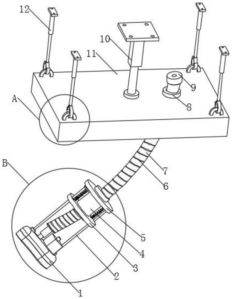
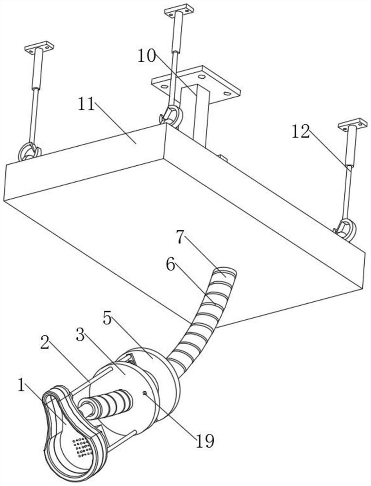
[0003] In the prior art, breathing masks are often used on the head and ears by means of elastic cords, but if the elastic cords are placed on the head and ears for a long time, it will cause pain, and the breathing mask needs to be manually touched to the face Or other positions of the patient's body can be used to wear the breathing mask tightly. When wearing it for people with infectious diseases, medical staff are also prone to infectious diseases, and the risk is greater; and some existing breathing masks are directly attached to the face to keep them tight However, it is easy to loosen, resulting in oxygen leakage and waste; some breathing masks are fixed on the face by negative pressure adsorption, but negative pressure adsorption requires real-time negative pressure suction, the cost is high, and it is easy to cause excessive compression damage to the pressed position of the face redness and swelling; for this reason we provide a breathing mask self-wearing mechanism and monitoring equipment based on the mechanism to solve the above problems

Method used


Image

  • Self-wearing mechanism for breathing mask and monitoring equipment based on self-wearing mechanism
  • Self-wearing mechanism for breathing mask and monitoring equipment based on self-wearing mechanism
  • Self-wearing mechanism for breathing mask and monitoring equipment based on self-wearing mechanism

Examples


Embodiment Construction

[0034] In order to make the object, technical solution and advantages of the present invention clearer, the present invention will be further described in detail below through the accompanying drawings and embodiments. However, it should be understood that the specific embodiments described here are only used to explain the present invention, and are not intended to limit the scope of the present invention.

[0035] It should be noted that when an element is said to be "disposed on, provided with" another element, it may be directly on the other element or there may also be an intermediate element. A component, it can be directly connected to another component or there may be an intermediate component at the same time. "Fixed connection" means fixed connection. There are many ways of fixed connection, which are not within the scope of protection of this article. The term used in this article "Vertical", "horizontal", "left", "right" and similar expressions are for the purpose ...


PUM


Abstract

The invention discloses a self-wearing mechanism for a breathing mask and monitoring equipment based on the self-wearing mechanism. The self-wearing mechanism includes a latex layer for improving theadhesion between the breathing mask and face, and the latex layer is internally provided with an elastic part capable of elastically supporting the latex layer to stick to the face, when the elastic part is elastically tightened, the breathing mask is fully fitted to the face, the latex layer is high in protection, and soft and comfortable when fitted to the face, compression injuries are not caused, a supporting tube supporting the breathing mask and capable of being plastically deformed is arranged above the breathing mask, the position of the breathing mask is adjusted when the supporting tube is plastically deformed, the supporting tube replaces an existing method of using elastic strings to tie the breathing mask to head or fixed on ears, tighten injuries are not caused, the supporting tube is conveniently and manually adjusted to realize the fixation of the breathing mask, touching of the body of a patient is not needed, that situation that the patient with the infectious diseasetransmits the infectious disease to a medical staff is avoided, and the safety is high.

Description

technical field [0001] The invention relates to the technical field of monitoring equipment, in particular to a breathing mask self-wearing mechanism and monitoring equipment based on the mechanism. Background technique [0002] Monitoring equipment is a device or system that measures and controls a patient's physiological parameters and can be compared with a known set value. If an alarm is exceeded, the monitoring equipment includes a breathing mask for providing oxygen breathing to the patient. [0003] In the prior art, breathing masks are often used on the head and ears through elastic cords, but the elastic cords on the head and ears will cause pain for a long time, and the breathing masks need to be manually touched to the face Or other positions of the patient's body can be used to wear the breathing mask tightly. When wearing it for people with infectious diseases, medical staff are also prone to infectious diseases, and the risk is greater; and some existing breath...

Claims


Application Information

Patent Timeline
IPC IPC(8): A61M16/06
CPCA61M16/06
Inventor 朱涛
Owner JIESHOU HUASHENG PLASTIC MACHINERY
Learn More