
Efficiently-mounted injection mold mechanism

An injection mold, high-efficiency technology, applied in the field of efficient installation of injection mold mechanism, can solve the problems of affecting production efficiency, time-consuming, cumbersome installation and disassembly process, etc., to save installation time, low maintenance difficulty, save installation or disassembly time Effect

Inactive Publication Date: 2020-09-29
秦喜顺
View PDF3 Cites 0 Cited by
  • Summary
  • Abstract
  • Description
  • Claims
  • Application Information

AI Technical Summary

Problems solved by technology

[0002] Injection mold is a type of mold that is often used in industrial production. The upper mold and lower mold of the injection mold are generally fixed on the mounting plate, and the existing installation method is to use the bolt structure to fix the upper mold or the lower mold. On the mounting plate, multiple screws need to be screwed to fix the mold during installation; since the mold is often replaced according to production needs or daily wear and tear, the method of bolt fixing is not only cumbersome to install and disassemble, but also takes a long time, seriously affecting Productivity

Method used


Image

  • Efficiently-mounted injection mold mechanism
  • Efficiently-mounted injection mold mechanism
  • Efficiently-mounted injection mold mechanism

Examples


Embodiment Construction

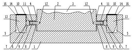
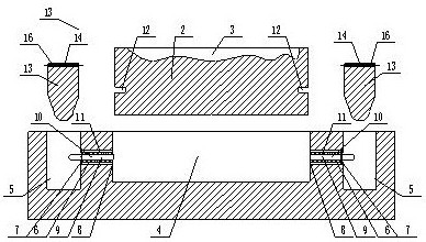
[0025] The present invention is specifically described below in conjunction with accompanying drawing, as Figure 1-4 shown;

[0026] The invention of the present application lies in that two long grooves 5 are arranged on the upper surface of the mounting plate, and the two long grooves are symmetrical about the mounting grooves. Hole 6, several through holes are located between the long groove and the installation groove, one end of the through hole communicates with the inner cavity of the installation groove, and the other end communicates with the inner cavity of the long groove, and the port where the through hole communicates with the long groove Rib one 7 is fixedly installed, and rib two 8 is fixedly installed at the port where the through hole communicates with the installation groove, and a cylinder 9 is installed in the through hole, and one end of the cylinder passes through the rib one and stretches into the elongated groove, and the cylinder The other end of th...


PUM


Abstract

The invention discloses an efficiently-mounted injection mold mechanism. The efficiently-mounted injection mold mechanism comprises a mounting plate and a mold; a mold cavity is formed in the surfaceof the mold, a mounting groove is formed in the mounting plate, the shape of the mounting groove is matched with that of the mold, the mold is mounted in the mounting groove, two long grooves are formed in the upper surface of the mounting plate, the two long grooves are symmetrical about the mounting groove, the long grooves are rectangular grooves, a plurality of through holes are formed in themounting plate and located between the long grooves and the mounting groove, one end of each through hole communicates with an inner cavity of the mounting groove, the other end of each through hole communicates with an inner cavity of the corresponding long groove, a first flange is fixedly mounted at the end opening, communicating with the corresponding long groove, of each through hole, a second flange is fixedly mounted at the end opening, communicated with the mounting groove, of each through hole, and a circle is mounted in each through hole. The efficiently-mounted injection mold mechanism has the beneficial effects that the structure is simple, and installation and dismounting are convenient and fast.

Description

technical field [0001] The invention relates to the technical field of injection mold installation, in particular to an injection mold mechanism for efficient installation. Background technique [0002] Injection mold is a type of mold often used in industrial production. The upper mold and lower mold of injection mold are generally fixedly installed on the mounting plate, and the existing installation method is to use the bolt structure to fix the upper mold or lower mold on the On the mounting plate, multiple screws need to be screwed to fix the mold during installation; since the mold is often replaced according to production needs or daily wear and tear, the method of bolt fixing is not only cumbersome to install and disassemble, but also takes a long time, seriously affecting Productivity. Contents of the invention [0003] The object of the present invention is to solve the above-mentioned problems, and to design an injection mold mechanism for efficient installatio...

Claims


Application Information

Patent Timeline
Patent Type & Authority Applications(China)
IPC IPC(8): B29C45/17
CPCB29C45/1742
Inventor 秦喜顺
Owner 秦喜顺
Learn More