
Display panel and display device

A display panel and display area technology, which is applied in nonlinear optics, instruments, optics, etc., can solve the problems of unfavorable narrow frame full screen design of display panel, occupation of non-display area of ​​display panel, etc.

Active Publication Date: 2020-09-25
XIAMEN TIANMA MICRO ELECTRONICS
View PDF5 Cites 3 Cited by
  • Summary
  • Abstract
  • Description
  • Claims
  • Application Information

AI Technical Summary

Problems solved by technology

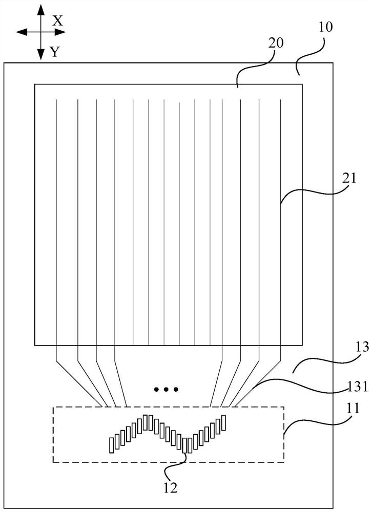
In general, the output bonding pads arranged in sequence are arranged in a straight line along a certain direction, so that a wider fan-out area needs to be formed between the bonding area and the display area for the layout of the fan-out line. The fan-out area will occupy the non-display area of ​​the display panel, which is not conducive to the narrow border full screen design of the display panel

Method used


Image

  • Display panel and display device
  • Display panel and display device
  • Display panel and display device

Examples


Embodiment Construction

[0024] The present invention will be further described in detail below in conjunction with the accompanying drawings and embodiments. It should be understood that the specific embodiments described here are only used to explain the present invention, but not to limit the present invention. In addition, it should be noted that, for the convenience of description, only some structures related to the present invention are shown in the drawings but not all structures.

[0025] An embodiment of the present invention provides a display panel, including: a display area and a non-display area surrounding the display area; the display area includes a plurality of signal lines extending along a first direction and arranged along a second direction; the first direction and the second direction Two directions intersect;

[0026] The non-display area includes a binding area for binding the driving chip; the binding area is provided with a first pad portion; the first pad portion includes ...


PUM


Abstract

The invention discloses a display panel and a display device. A binding area of the display panel is provided with a first bonding pad part; the first bonding pad part comprises at least two first subbonding pad parts and at least one second sub bonding pad part, or at least one first sub bonding pad part and at least two second sub bonding pad parts; the first sub-pad parts and the second sub-pad parts are alternately arranged in a second direction; each first sub bonding pad part comprises at least one first inclined section; the first first bonding pad and the last first bonding pad in thefirst inclined section are defined to form a first connecting line; each second sub-pad part comprises at least one second inclined section, and the first first pad and the last first pad in the second inclined section are defined to form a second connecting line; in the clockwise direction, the included angle between the second direction and the first connecting line is an acute angle; and in the anticlockwise direction, the included angle between the second direction and the second connecting line is an acute angle. According to the technical scheme provided by the invention, the narrow-bezel design of the display panel is realized.

Description

technical field [0001] The present invention relates to the field of display technology, in particular to a display panel and a display device. Background technique [0002] Currently, various types of display panels such as liquid crystal display panels and organic light emitting display panels have been developed on the market. The above-mentioned display panel includes a display area provided with a pixel unit array, and a non-display area provided with a driving chip for driving the pixel unit array. [0003] In the current common process, the driver chip is separately manufactured in the form of a chip, and the driver chip is directly bound on the glass substrate of the display panel by a chip on glass (chip on glass, COG) mounting method. The display panel corresponding to the above installation method is provided with input bonding pads and output bonding pads for bonding the driver chip. In general, the output bonding pads arranged in sequence are arranged in a str...

Claims


Application Information

Patent Timeline
IPC IPC(8): G02F1/1345
CPCG02F1/13458G02F1/1345
Inventor 杨毅志
Owner XIAMEN TIANMA MICRO ELECTRONICS
Learn More