
Automatic train unhooking device

A hook device and automatic technology are applied in the field of automatic hook removal devices for trains, which can solve problems such as hidden safety hazards, lower discharge efficiency, and hook lifting rod grabbing, etc., and achieve the effects of high degree of automation, reduced work intensity, and improved work efficiency.

Pending Publication Date: 2020-09-25
大连轩泰重工有限公司
View PDF0 Cites 4 Cited by
  • Summary
  • Abstract
  • Description
  • Claims
  • Application Information

AI Technical Summary

Problems solved by technology

[0002] The train carriages need to be separated before unloading, transshipment or reorganization. This work currently requires manual operation of the train hook to separate the train carriages. Currently, the train dumping system is fully automatic. There is a big safety hazard in the operation of lifting the hook; at the same time, it is difficult to connect with the overturning system in the unhooking work with manual participation, which not only reduces the stability of the train unloading system, but also greatly reduces the unloading efficiency;
[0003] Existing unhooking technology: 1. The existing unhooking equipment has a large volume and cannot be unhooked in the narrow space of the adjacent carriage; 3. The existing dehooking equipment requires the train to stop at a fixed position before dehooking, which cannot be matched with the current unloading system; Under long-term human operation, the hook lifting rod is partially bent and deformed, and the existing hook removal cannot grasp the hook lifting rod, and the hook removal cannot be completed; 5. During the stop process of the carriage, there is a stretching or compression jam of the coupler The existing hook removal equipment performs the hook removal operation on the hook lever, even if the hook lever is rotated and deformed, it cannot complete the operation of separating the carriage

Method used


Image

  • Automatic train unhooking device
  • Automatic train unhooking device
  • Automatic train unhooking device

Examples


Embodiment Construction

[0036] In order to make the technical problems solved by the present invention, the technical solutions adopted and the technical effects achieved clearer, the present invention will be further described in detail below in conjunction with the accompanying drawings and embodiments. It should be understood that the specific embodiments described here are only used to explain the present invention, but not to limit the present invention. In addition, it should be noted that, for the convenience of description, only parts related to the present invention are shown in the drawings but not all content.

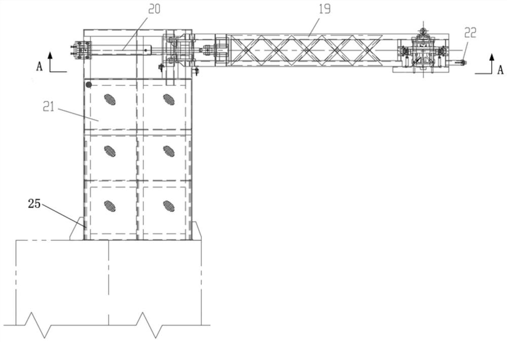
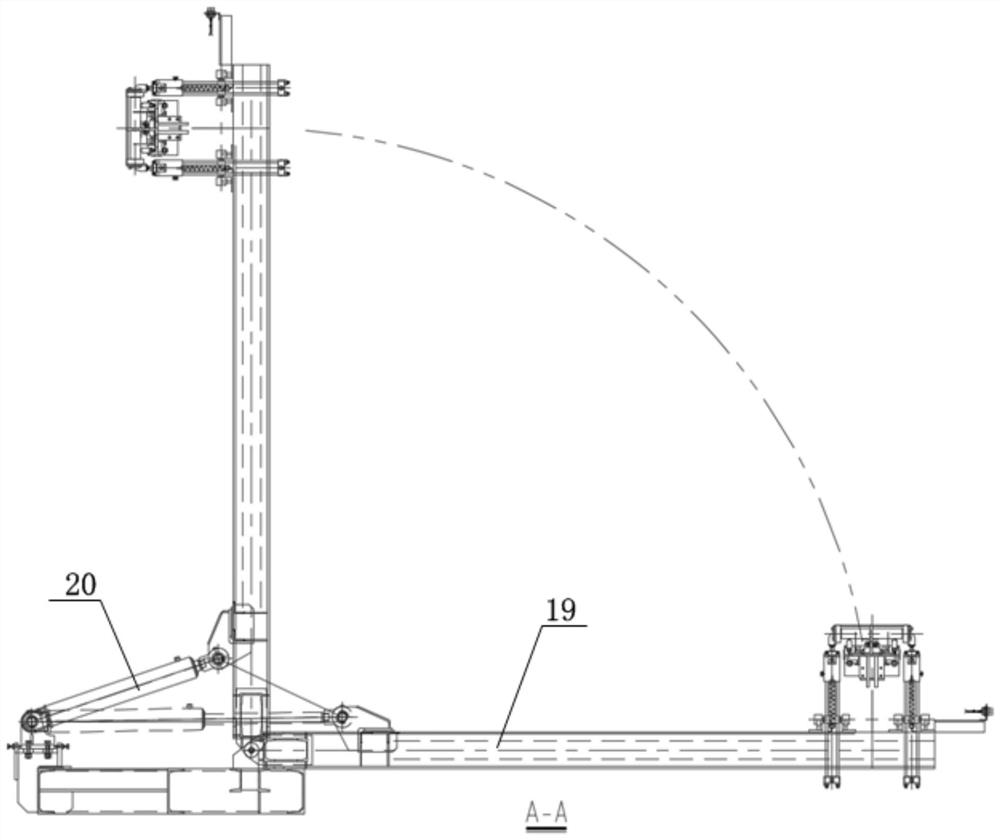
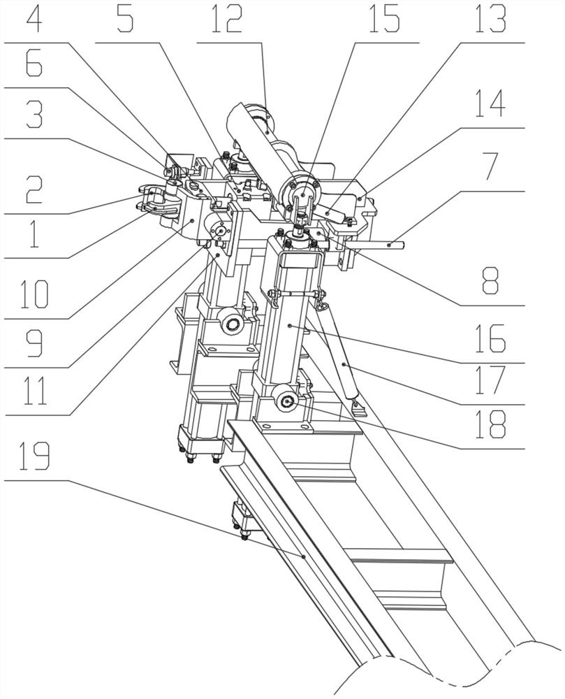
[0037] figure 1 It is a structural schematic diagram of the automatic decoupling device for trains provided by the present invention; figure 2 yes figure 1 Middle A-A sectional view. Such as Figure 1-2 As shown, the automatic decoupling device for trains provided by the embodiment of the present invention includes: a large inclination angle clamping mechanism, a hook decoupli...


PUM


Abstract

The invention relates to the field of railway traffic auxiliary equipment, and provides an automatic train unhooking device which comprises a large-dip-angle clamping mechanism, an unhooking rotatingmechanism, a rotary lifting mechanism and a large arm pitching mechanism. The large-dip-angle clamping mechanism comprises a left clamp, a right clamp, a fixed pin shaft, a clamp connecting base, a clamp oil cylinder, a clamp frame, a clamp push-out oil cylinder and a push-out oil cylinder base. A cylinder body of the clamp push-out oil cylinder is arranged on the push-out oil cylinder base, and apiston rod of the clamp push-out oil cylinder is fixedly connected with the clamp frame. The fixed pin shaft is arranged on the clamp frame; a cylinder body of the clamp oil cylinder is arranged on the clamp frame, and a piston rod of the clamp oil cylinder is fixedly connected with the clamp connecting base. The left clamp and the right clamp are hinged to the clamp connecting base. The left clamp and the right clamp are hinged to the fixed pin shaft and extend out of the clamp frame. The device is high in automation degree, the working intensity of workers is reduced, and the working efficiency is improved.

Description

technical field [0001] The invention relates to the field of railway traffic auxiliary equipment, in particular to an automatic decoupling device for trains. Background technique [0002] It is necessary to separate the train carriages before unloading, transshipment or reorganization. This work currently requires manual operation of the train hook to separate the train carriages. Currently, the train dumping system is fully automatic. There is a big safety hazard in the operation of lifting the hook; at the same time, it is difficult to connect with the overturning system in the hook removal work with manual participation, which not only reduces the stability of the train unloading system, but also greatly reduces the unloading efficiency; [0003] Existing unhooking technology: 1. The existing unhooking equipment has a large volume and cannot be unhooked in the narrow space of the adjacent carriage; 3. The existing dehooking equipment requires the train to stop at a fixed...

Claims


Application Information

Patent Timeline
Patent Type & Authority Applications(China)
IPC IPC(8): B61G7/04
CPCB61G7/04
Inventor 李绍杰焦修堃郑立燕李宁
Owner 大连轩泰重工有限公司
Learn More