
Control terminal-based cab convenient for seat adjustment and used for engineering machinery

A technology for construction machinery and cabs, applied in the field of cabs, can solve problems such as difficulty in taking a good rest, and achieve the effect of reducing driving fatigue and simple and quick operation.

Active Publication Date: 2020-09-25
江苏特能鼎特种装备制造有限公司
View PDF6 Cites 0 Cited by
  • Summary
  • Abstract
  • Description
  • Claims
  • Application Information

AI Technical Summary

Problems solved by technology

[0004] The object of the present invention is to provide a cab for construction machinery based on the control terminal to facilitate seat adjustment, so as to solve the problem that the horizontal placement of the legs is difficult to properly rest problem

Method used


Image

  • Control terminal-based cab convenient for seat adjustment and used for engineering machinery
  • Control terminal-based cab convenient for seat adjustment and used for engineering machinery
  • Control terminal-based cab convenient for seat adjustment and used for engineering machinery

Examples


Embodiment 1

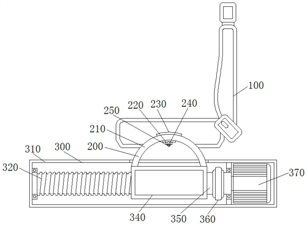
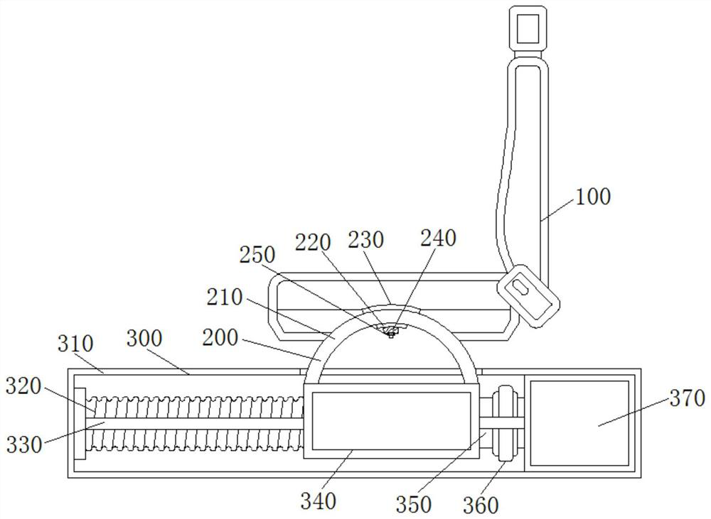
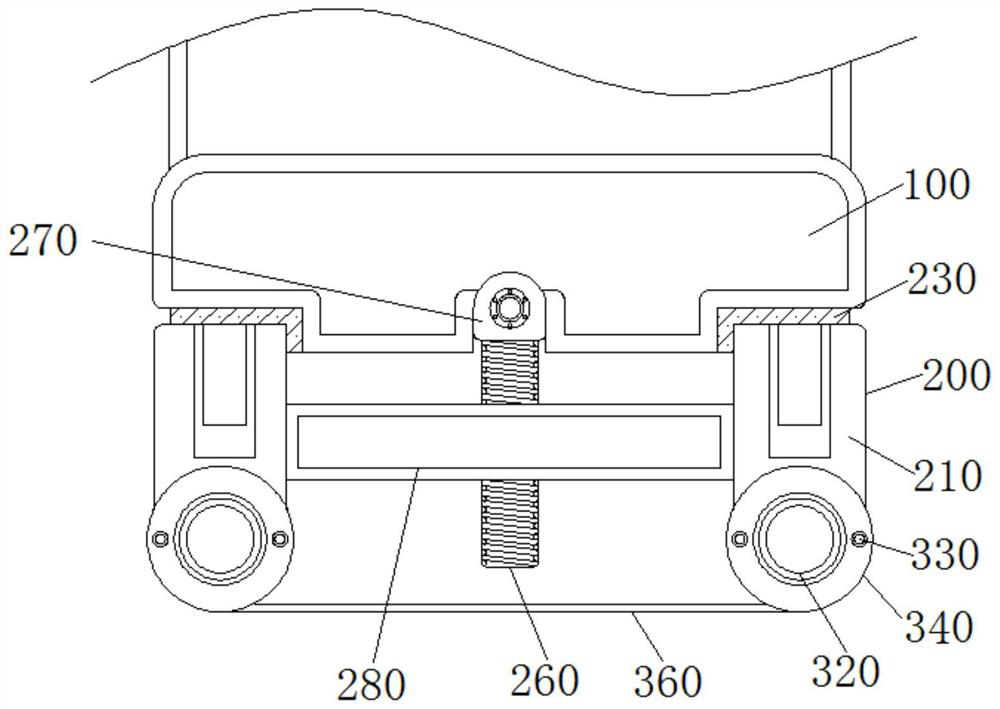
[0028] A driver's cab for construction machinery based on a control terminal to facilitate seat adjustment, including a seat body 100, the bottom end of the seat body 100 is connected with a corner mechanism 200, and the corner mechanism 200 includes a first fixing block 210, a first connecting block 220, The second connecting block 230, the third connecting block 240, the bolt 250, the worm wheel 260, the second fixing block 270, the first fixing rod 280, the first motor 290, the connecting shaft 2100, the second fixing rod 2110, the worm 2120 and the third Fixed rod 2130, the top of the first fixed block 210 is connected with the second connecting block 230, and the bottom end of the second connecting block 230 is fixed with the third fixed rod 2130, the first fixed block 210 is provided with two groups, and the first fixed The block 210 has a semicircular structure. The first fixed block 210 is symmetrically distributed under the seat body 100. A groove is opened inside the ...

Embodiment 2

[0033]Embodiment 2: A cab for construction machinery based on a control terminal to facilitate seat adjustment, including a seat body 100, the bottom end of the seat body 100 is connected with a corner mechanism 200, and the corner mechanism 200 includes a first fixed block 210, a first Connecting block 220, second connecting block 230, third connecting block 240, bolt 250, worm gear 260, second fixing block 270, first fixing rod 280, first motor 290, connecting shaft 2100, second fixing rod 2110, worm 2120 and the third fixed rod 2130, the top of the first fixed block 210 is connected with the second connecting block 230, and the bottom end of the second connecting block 230 is fixed with the third fixed rod 2130, the first fixed block 210 is provided with two groups, And the first fixed block 210 is a semicircular structure, the first fixed block 210 is symmetrically distributed under the seat body 100, the first fixed block 210 enables the seat body 100 to rotate at an overa...


PUM


Abstract

The invention belongs to the technical field of seats and relates to a control terminal-based cab convenient for seat adjustment and used for engineering machinery. The cab comprises a seat body; thebottom end of the seat body is connected with a corner mechanism; the corner mechanism comprises a first fixing block, a first connecting block, a second connecting block, a third connecting block, abolt, a worm wheel, a second fixing block, a first fixing rod, a first motor, a connecting rotating shaft, a second fixing rod, a worm and a third fixing rod; the top end of the first fixing block isconnected with the second connecting block; the third fixing rod is fixed to the bottom end of the second connecting block; the surface of the side, away from the second connecting block, of the thirdfixing rod is sleeved with the first connecting block. The seat is provided with the corner mechanism, the position of the seat body integrally rotates, the legs of a driver incline along with the upper half body, so that the driver can have a good rest; the horizontal position of the seat body can be rapidly adjusted through a translation mechanism, and operation is easy and rapid.

Description

technical field [0001] The invention relates to the technical field of seats, in particular to a cab for engineering machinery that is convenient for seat adjustment based on a control terminal. Background technique [0002] With the continuous development of society, the correct driving posture can effectively protect the driver's safety. If the driver's seat is not in the right position, it will affect the driver's sight and control sensitivity, and even cause traffic accidents. As cars gradually become humanized, Today, with the development of comfort, the research on the adjustment of car driving seats cannot be ignored. [0003] Existing seats are usually manually adjusted, and the existing seats can only adjust the distance in the horizontal direction and the vertical direction. However, the seat remains horizontal, making the driver's upper body reclining and his legs level, which makes it difficult for the driver to take a good rest, thus increasing the driver's dri...

Claims


Application Information

Patent Timeline
Patent Type & Authority Applications(China)
IPC IPC(8): B60N2/02B60N2/10B60N2/22B60N2/04B60N2/38B62D33/06
CPCB60N2/10B60N2/22B60N2/04B60N2/38B62D33/0617B60N2/02246
Inventor 白者叶
Owner 江苏特能鼎特种装备制造有限公司
Learn More